G5N120CN Просмотр технического описания (PDF) - Fairchild Semiconductor
Номер в каталоге
Компоненты Описание
производитель
G5N120CN Datasheet PDF : 7 Pages
| |||
HGTP5N120CN, HGT1S5N120CNS
Electrical Specifications TC = 25oC, Unless Otherwise Specified (Continued)
PARAMETER
SYMBOL
TEST CONDITIONS
MIN
TYP
MAX UNITS
Current Turn-On Delay Time
Current Rise Time
Current Turn-Off Delay Time
Current Fall Time
Turn-On Energy (Note 3)
td(ON)I
trI
td(OFF)I
tfI
EON1
IGBT and Diode at TJ = 25oC
ICE = 5.5A
VCE = 960V
VGE = 15V
RG = 25Ω
L = 5mH
Test Circuit (Figure 18)
-
22
30
ns
-
12
16
ns
-
180
250
ns
-
280
350
ns
-
220
-
µJ
Turn-On Energy (Note 3)
EON2
-
400
500
µJ
Turn-Off Energy (Note 4)
Current Turn-On Delay Time
Current Rise Time
Current Turn-Off Delay Time
Current Fall Time
Turn-On Energy (Note 3)
EOFF
td(ON)I
trI
td(OFF)I
tfI
EON1
IGBT and Diode at TJ = 150oC
ICE = 5.5A
VCE = 960V
VGE = 15V
RG = 25Ω
L = 5mH
Test Circuit (Figure 18)
-
640
700
µJ
-
20
25
ns
-
12
16
ns
-
225
300
ns
-
350
400
ns
-
220
-
µJ
Turn-On Energy (Note 3)
EON2
-
1
1.2
mJ
Turn-Off Energy (Note 4)
Thermal Resistance Junction To Case
EOFF
RθJC
-
1
1.1
mJ
-
-
0.75
oC/W
NOTES:
3. Values for two Turn-On loss conditions are shown for the convenience of the circuit designer. EON1 is the turn-on loss of the IGBT only. EON2
is the turn-on loss when a typical diode is used in the test circuit and the diode is at the same TJ as the IGBT. The diode type is specified in
Figure 18.
4. Turn-Off Energy Loss (EOFF) is defined as the integral of the instantaneous power loss starting at the trailing edge of the input pulse and ending
at the point where the collector current equals zero (ICE = 0A). All devices were tested per JEDEC Standard No. 24-1 Method for Measurement
of Power Device Turn-Off Switching Loss. This test method produces the true total Turn-Off Energy Loss.
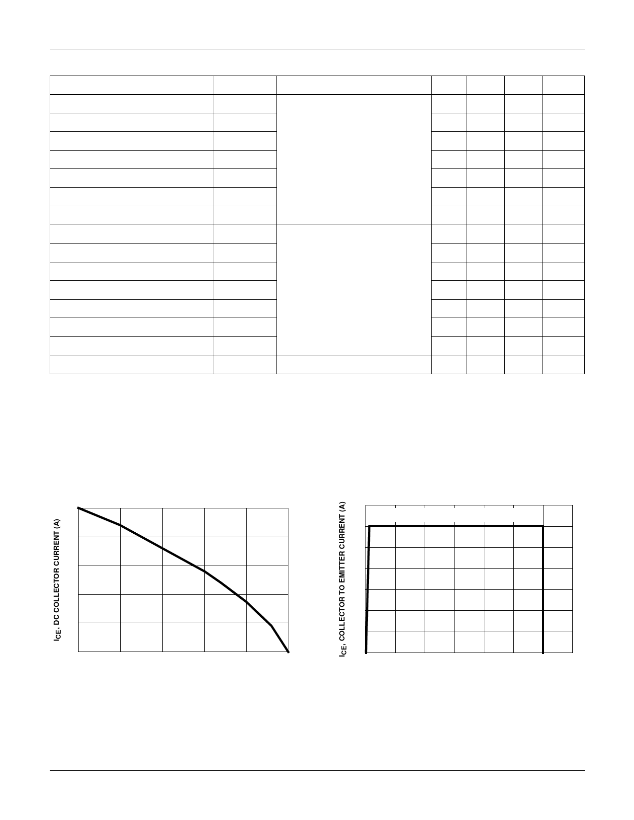
Typical Performance Curves Unless Otherwise Specified
25
VGE = 15V
20
15
10
5
0
25
50
75
100
125
150
TC, CASE TEMPERATURE (oC)
FIGURE 1. DC COLLECTOR CURRENT vs CASE
TEMPERATURE
35
TJ = 150oC, RG = 25Ω, VGE = 15V, L = 200µH
30
25
20
15
10
5
0
0
200 400 600 800 1000 1200 1400
VCE, COLLECTOR TO EMITTER VOLTAGE (V)
FIGURE 2. MINIMUM SWITCHING SAFE OPERATING AREA
©2001 Fairchild Semiconductor Corporation
HGTP5N120CN, HGT1S5N120CNS Rev. B
Share Link: 