AA028P2-00 Просмотр технического описания (PDF) - Skyworks Solutions
Номер в каталоге
Компоненты Описание
производитель
AA028P2-00 Datasheet PDF : 3 Pages
| |||
27–31 GHz GaAs MMIC
Driver Amplifier
Features
■ Single Bias Supply Operation (6 V)
■ 14 dB Typical Small Signal Gain
■ 16 dBm Typical P1 dB Output Power
at 28 GHz
■ 0.25 µm Ti/Pd/Au Gates
■ 100% On-Wafer RF and DC Testing
■ 100% Visual Inspection to MIL-STD-883
MT 2010
Description
Skyworks’ two-stage reactively-matched 27–31 GHz GaAs
MMIC driver amplifier has typical small signal gain of
14 dB with a typical P1 dB of 16 dBm at 28 GHz. The chip
uses Skyworks’ proven 0.25 µm MESFET technology, and
is based upon MBE layers and electron beam lithography
for the highest uniformity and repeatability. The FETs
employ surface passivation to ensure a rugged, reliable
part with through-substrate via holes and gold-based
backside metallization to facilitate a conductive epoxy die
attach process. All chips are screened for gain, output
power and S-parameters prior to shipment for guaranteed
performance. Designed for 27–31 GHz LMDS and digital
radio bands.
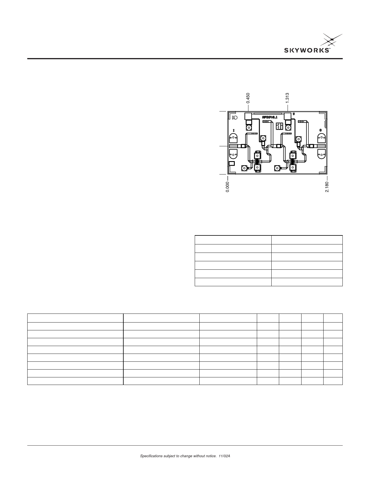
Chip Outline
1.380
AA028P2-00
0.617
0.000
Dimensions indicated in mm.
All DC (V) pads are 0.1 x 0.1 mm and RF In, Out pads are 0.07 mm wide.
Chip thickness = 0.1 mm.
Absolute Maximum Ratings
Characteristic
Operating Temperature (TC)
Storage Temperature (TST)
Bias Voltage (VD)
Power In (PIN)
Junction Temperature (TJ)
Value
-55°C to +90°C
-65°C to +150°C
7 VDC
16 dBm
175°C
Electrical Specifications at 25°C (VDS = 6 V)
Parameter
Condition
Drain Current
Small Signal Gain
F = 27–31 GHz
Input Return Loss
F = 27–31 GHz
Output Return Loss
F = 27–31 GHz
Output Power at 1 dB Gain Compression
F = 28 GHz
Saturated Output Power
Two-Tone Output Third-Order Intercept1
Thermal Resistance2
F = 28 GHz
F = 28 GHz
1. Not measured on a 100% basis.
2. Calculated value based on measurement of discrete FET.
3. Typical represents the median parameter value across the specified
frequency range for the median chip.
Symbol
IDS
G
RLI
RLO
P1 dB
PSAT
OIP3
ΘJC
Min.
12
13
14
Typ.3
80
14
-11
-12
16
17
26.5
198
Max.
110
-6
-6
Unit
mA
dB
dB
dB
dBm
dBm
dBm
°C/W
Skyworks Solutions, Inc. [781] 376-3000 • Fax [781] 376-3100 • Email sales@skyworksinc.com • www.skyworksinc.com
1
Specifications subject to change without notice. 11/02A
Share Link: 