HCF4097BM1 Просмотр технического описания (PDF) - STMicroelectronics
Номер в каталоге
Компоненты Описание
производитель
HCF4097BM1 Datasheet PDF : 10 Pages
| |||
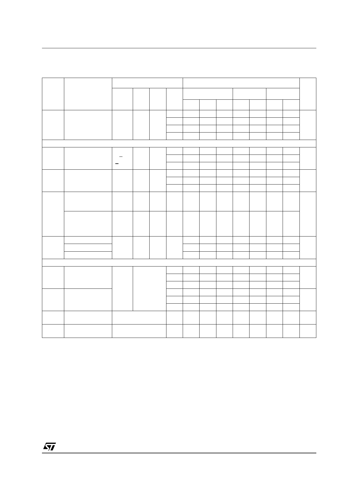
HCF4097B
STATIC ELECTRICAL CHARACTERISTICS
(Tamb = 25°C,Typical temperature coefficient for all VDD value is 0.3 %/°C)
Test Condition
Value
Symbol Parameter
VIS
VEE VSS VDD
TA = 25°C
-40 to 85°C -55 to 125°C Unit
(V) (V) (V) (V) Min. Typ. Max. Min. Max. Min. Max.
IL Quiescent Supply
Current
5
0.04 5
150
150
10
0.04 10
300
300
µA
15
0.04 20
600
600
20
0.08 100
3000
3000
SWITCH
RON On Resistance
0 < VI
< VDD
0
5
0 10
15
470 1050
180 400
125 240
1200
500
300
1200
520 Ω
300
∆ON Resistance ∆RON
5
10
(between any 2 of
0
0 10
10
Ω
4 switches)
15
5
OFF (•) Channel Leakage
Current Any
Channel Off
Channel Leakage
Current All
Channel Off
(Common Out/In)
0
0 18
0
0 18
±0.1 100
±0.1 100
1000
1000
1000
µA
1000
C Capacitance Input
5
Output capacitance
-5 5
35
pF
Feedthrough
0.2
CONTROL
VIL Input Low Voltage
VEE = VSS
5
= VDD
thru
RL = 1KΩ to
VSS
10
15
VIH Input High Voltage 1KΩ IIS < 2µA (on 5 3.5
all OFF
10 7
channels) 15 11
1.5
1.5
1.5
3
3
3
V
4
4
4
3.5
3.5
7
7
V
11
11
II Input Leakage
Current
VI = 0/18V
18
±10-3 ±0.1
±1
±1 µA
CI Input Capacitance Any Address or Inhibit
Input
5 7.5
pF
The Noise Margin for both "1" and "0" level is: 1V min. with VDD=5V, 2V min. with VDD=10V, 2.5V min. with VDD=15V
• Determined by minimum feasible leakage measurement for automating testing
5/10
Share Link: 