H1100I Просмотр технического описания (PDF) - Intersil
Номер в каталоге
Компоненты Описание
производитель
H1100I Datasheet PDF : 10 Pages
| |||
HFA1100
Application Information
Optimum Feedback Resistor (RF)
The enclosed plots of inverting and non-inverting frequency
response detail the performance of the HFA1100 in various
gains. Although the bandwidth dependency on ACL isn’t as
severe as that of a voltage feedback amplifier, there is an
appreciable decrease in bandwidth at higher gains. This
decrease can be minimized by taking advantage of the
current feedback amplifier’s unique relationship between
bandwidth and RF. All current feedback amplifiers require a
feedback resistor, even for unity gain applications, and the
RF, in conjunction with the internal compensation capacitor,
sets the dominant pole of the frequency response. Thus, the
amplifier’s bandwidth is inversely proportional to RF. The
HFA1100 design is optimized for a 510Ω RF, at a gain of +1.
Decreasing RF in a unity gain application decreases stability,
resulting in excessive peaking and overshoot (Note:
Capacitive feedback causes the same problems due to the
feedback impedance decrease at higher frequencies). At
higher gains the amplifier is more stable, so RF can be
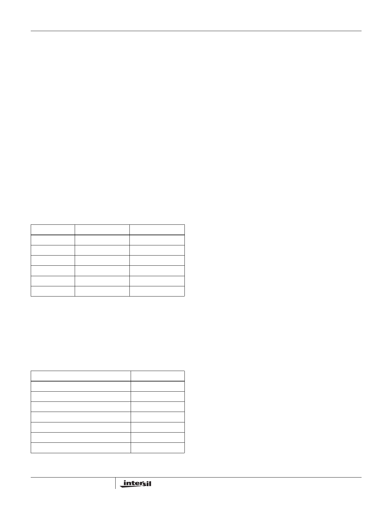
decreased in a trade-off of stability for bandwidth. The table
below lists recommended RF values for various gains, and the
expected bandwidth.
ACL
RF (Ω)
BW (MHz)
+1
510
850
-1
430
580
+2
360
670
+5
150
520
+10
180
240
+19
270
125
5V Single Supply Operation
This amplifier operates at single supply voltages down to
4.5V. The table below details the amplifier’s performance
with a single 5V supply. The dramatic supply current
reduction at this operating condition (refer also to Figure 23)
makes these op amps even better choices for low power 5V
systems. Refer to Application Note AN9745 for further
information.
PARAMETER
Input Common Mode Range
-3dB BW (AV = +2)
Gain Flatness (to 50MHz, AV = +2)
Output Voltage (AV = -1)
Slew Rate (AV = +2)
0.1% Settling Time
Supply Current
TYP
1V to 4V
267MHz
0.05dB
1.3V to 3.8V
475V/µs
17ns
5.5mA
Use of Die in Hybrid Applications
This amplifier is designed with compensation to negate the
package parasitics that typically lead to instabilities. As a
result, the use of die in hybrid applications results in
overcompensated performance due to lower parasitic
capacitances. Reducing RF below the recommended values
for packaged units will solve the problem. For AV = +2 the
recommended starting point is 300Ω, while unity gain
applications should try 400Ω.
PC Board Layout
The frequency performance of this amplifier depends a great
deal on the amount of care taken in designing the PC board.
The use of low inductance components such as chip
resistors and chip capacitors is strongly recommended,
while a solid ground plane is a must!
Attention should be given to decoupling the power supplies.
A large value (10µF) tantalum in parallel with a small value
chip (0.1µF) capacitor works well in most cases.
Terminated microstrip signal lines are recommended at the
input and output of the device. Output capacitance, such as
that resulting from an improperly terminated transmission
line will degrade the frequency response of the amplifier and
may cause oscillations. In most cases, the oscillation can be
avoided by placing a resistor in series with the output.
Care must also be taken to minimize the capacitance to ground
seen by the amplifier’s inverting input. The larger this
capacitance, the worse the gain peaking, resulting in pulse
overshoot and possible instability. To this end, it is
recommended that the ground plane be removed under traces
connected to pin 2, and connections to pin 2 should be kept as
short as possible.
An example of a good high frequency layout is the
Evaluation Board shown below.
Evaluation Board
An evaluation board is available for the HFA1100 (Part
Number HFA11XXEVAL). Please contact your local sales
office for information.
4
FN2945.9
Share Link: 