RF2132 Просмотр технического описания (PDF) - RF Micro Devices
Номер в каталоге
Компоненты Описание
производитель
RF2132 Datasheet PDF : 6 Pages
| |||
RF2132
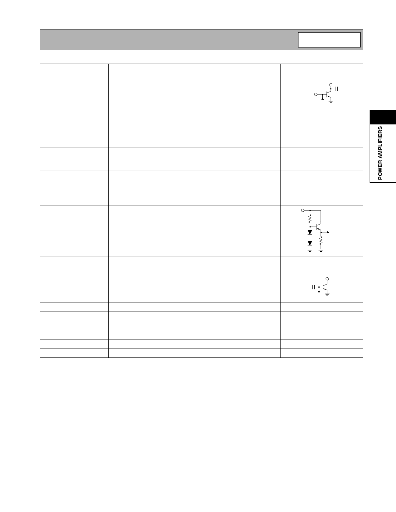
Pin Function Description
Interface Schematic
1
VCC1
Power supply for the driver stage, and interstage matching. Shunt
VCC
inductance is required on this pin, which can be achieved by an induc-
tor to VCC, with a decoupling capacitor on the VCC side. The value of
the inductor is frequency dependent; 3.3nH is required for 830MHz,
RF IN
and 1.2nH for 950MHz. Instead of an inductor, a high impedance
microstrip line can be used.
From Bias
Stages
2
NC
Not Connected.
2
3
RF IN
RF input. This is a 50Ω input, but the actual input impedance depends See pin 1.
on the interstage matching network connected to pin 1. An external DC
blocking capacitor is required if this port is connected to a DC path to
ground or a DC voltage.
4
GND
Ground connection. Keep traces physically short and connect immedi-
ately to the ground plane for best performance.
5
GND
Same as pin 4.
6
GND
Ground for stage 1. Keep traces physically short and connect immedi-
ately to ground plane for best performance. This ground should be iso-
lated from the batwing and other ground contacts. See evaluation
board layout.
7
GND
Same as pin 6.
8
PC
Power Control. When this pin is "low", all circuits are shut off. A "low" is
PC
typically 0.5V or less at room temperature. During normal operation
this pin is the power control. Control range varies from about 2V for
0dBm to VCC for +31dBm RF output power. The maximum power that
can be achieved depends on the actual output matching. PC should
never exceed 5.0V or VCC, whichever is the lowest.
To RF
Transistors
9
GND
Same as pin 4.
10
RF OUT RF Output and power supply for the output stage. The four output pins
are combined, and bias voltage for the final stage is provided through
these pins. The external path must be kept symmetric until combined to
ensure stability. An external matching network is required to provide the
optimum load impedance; see the application schematics for details.
RF OUT
From Bias
Stages
11
RF OUT Same as pin 10.
See pin 10.
12
GND
Same as pin 4.
13
GND
Same as pin 4.
14
RF OUT Same as pin 10.
See pin 10.
15
RF OUT Same as pin 10.
See pin 10.
16
GND
Same as pin 4.
Rev B9 010417
2-111
Share Link: 