MAX6745 –ü—Ä–æ—Å–º–æ—Ç—Ä —Ç–µ—Ö–Ω–∏—á–µ—Å–∫–æ–≥–æ –æ–ø–∏—Å–∞–Ω–∏—è (PDF) - Maxim Integrated
–ù–æ–º–µ—Ä –≤ –∫–∞—Ç–∞–ª–æ–≥–µ
–ö–æ–º–ø–æ–Ω–µ–Ω—Ç—ã –û–ø–∏—Å–∞–Ω–∏–µ
–ø—Ä–æ–∏–∑–≤–æ–¥–∏—Ç–µ–ª—å
MAX6745 Datasheet PDF : 16 Pages
| |||
Low-Power Dual-/Triple-Voltage SC70 µP
Supervisory Circuits
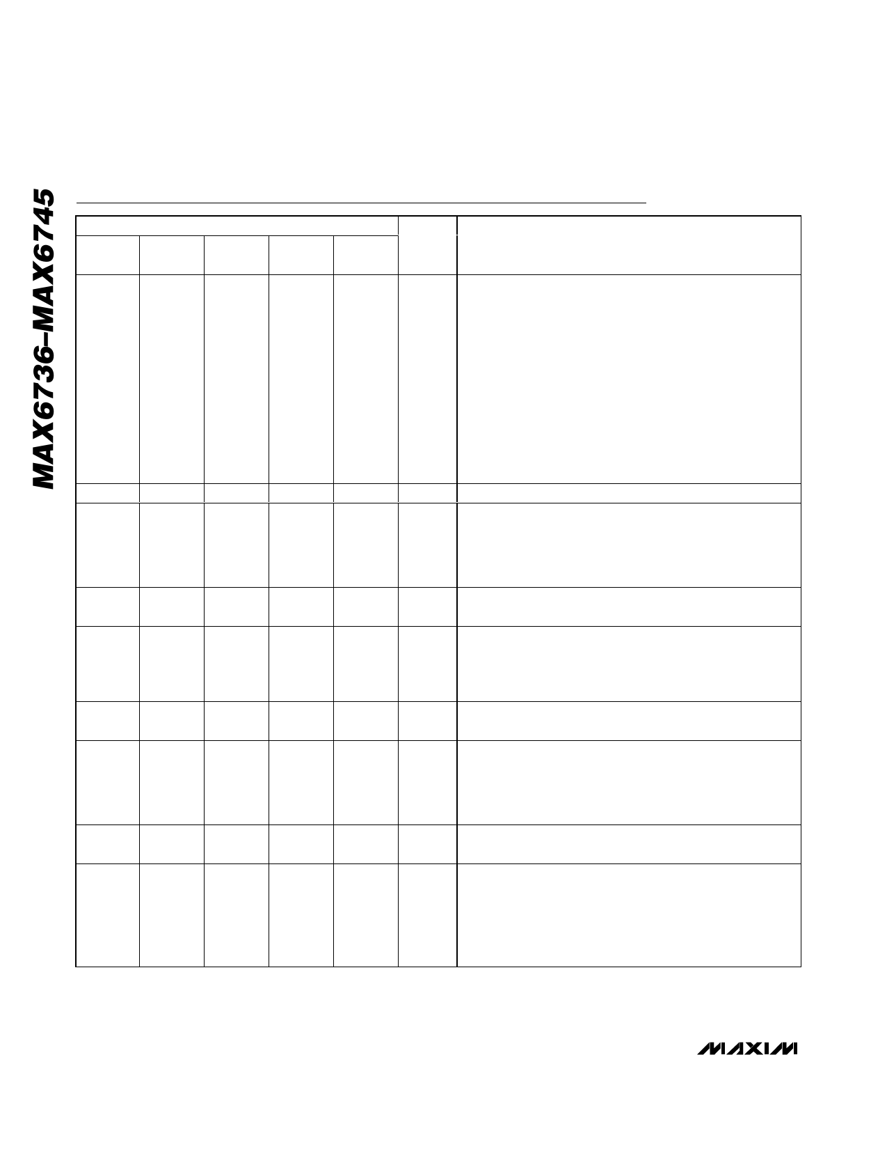
Pin Description
PIN
MAX6736 MAX6738 MAX6740 MAX6741 MAX6742
MAX6737 MAX6739 MAX6743 MAX6744 MAX6745
NAME
1
1
1
1
1
RESET
2
2
2
2
2
GND
3
3
—
—
—
MR
4
—
4
4
—
VCC2
—
4
3
—
—
RSTIN
5
5
5
5
5
VCC1
—
—
—
—
4
PFI
—
—
—
—
3
PFO
—
—
—
3
—
POK1
FUNCTION
Reset Output, Push-Pull or Open Drain Active Low. RESET
changes from high to low when any monitored power-supply
input (VCC1, VCC2, RSTIN) drops below its selected reset
threshold. It remains low until all monitored power-supply
inputs exceed their selected reset thresholds for the VCC
reset timeout period. RESET is forced low if MR is low for at
least the MR minimum input pulse width. It remains low for
the MR reset timeout period after MR goes high. The push-
pull output is referenced to VCC1. The MAX6736/MAX6738
open-drain outputs require an external pullup resistor. The
MAX6740/MAX6741/MAX6742 open-drain outputs have an
internal 50kΩ pullup resistor to VCC1 and provide a manual
reset function.
Ground
Manual Reset, Active Low. Pull low for at least MR minimum
input pulse width to force RESET low. Reset remains active
as long as MR is low and for the MR reset timeout period
after MR goes high. There is an internal 1.5kΩ pullup resistor
to VCC1.
Voltage Input 1. Power supply and input for the secondary
µP voltage reset monitor.
Adjustable Reset Threshold Input. RESET is asserted when
RSTIN is below the internal 0.488V reference level. Set the
adjustable reset threshold with an external resistor-divider
network. Connect RSTIN to VCC1 if unused.
Voltage Input 2. Power supply and input for the primary µP
voltage reset monitor.
Power-Fail Comparator Input. PFO is asserted when PFI is
below 0.488V. PFO is deasserted without any reset timeout
period when PFI goes above 0.488V. Connect PFI to an
external resistor network to set the desired monitor
threshold.
Power-Fail Comparator Output, Open Drain Active Low. PFO
is asserted when PFI is below 0.488V.
VCC1 Power-OK Output, Open Drain Active High. POK1
remains low as long as VCC1 is below VTH1. POK1 output
goes high after VCC1 exceeds VTH1 for the POK1 timeout
period. POK1 logic is independent of the MR or VCC2 inputs.
The output can be used to control VCC1-to-VCC2 supply
sequencing.
8 _______________________________________________________________________________________
Share Link: 