EN5335QI Просмотр технического описания (PDF) - Altera Corporation
Номер в каталоге
Компоненты Описание
производитель
EN5335QI Datasheet PDF : 15 Pages
| |||
EN5335QI
Theory of Operation
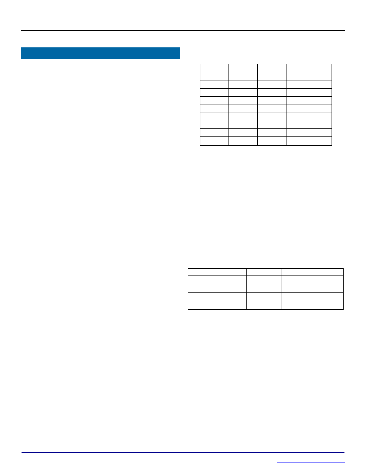
Table 1: Output Voltage Select Table:
Synchronous Buck Converter
The EN5335QI is a synchronous, pin
programmable power supply with integrated
power MOSFET switches and integrated
inductor. The nominal input voltage range is 2.4-
5.0V. The output can be set to common pre-set
voltages by connecting appropriate combinations
of 3 voltage selection pins to ground. The
feedback control loop is a type III voltage-mode
and the part uses a low-noise PWM topology. Up
to 3A of output current can be drawn from this
converter. The 5MHz operating frequency
enables the use of small-size output capacitors.
The power supply has the following protection
features:
Over-current protection (to protect the IC
from excessive load current)
Thermal shutdown with hysteresis
Over-voltage protection
Under-voltage lockout circuit to disable the
converter output when the input voltage is
less than approximately 2.2V
VS2*
0
0
0
0
1
1
1
1
VS1*
0
0
1
1
0
0
1
1
VS0* Output Voltage
0
3.3V
1
2.5V
0
1.8V
1
1.5V
0
1.25V
1
1.2V
0
0.8V
1
Reserved
Input Capacitor Selection
The EN5335QI requires about 20uF of input
capacitance. Low-cost, low-ESR ceramic
capacitors should be used as input capacitors for
this converter. The dielectric must be X5R or
X7R rated. In some applications, lower value
capacitors are needed in parallel with the larger,
capacitors in order to provide high frequency
decoupling. It is recommended to use 10V rated
MLCC capacitors.
Table 2. Recommended input capacitors.
Additional features include:
Soft-start circuit, limiting the in-rush
current when the converter is powered up
Power good circuit indicating whether the
output voltage is within 90% - 120% of the
programmed voltage
Output Voltage Programming
The EN5335QI output voltage is programmed
using a 3-pin voltage-ID or VID selector. Three
binary VID pins allow the user to choose one of
seven pre-set voltages. Refer to Table 1 for the
proper VID pin settings to choose VOUT.
Description
10uF, 10V, 10%
X7R, 1206
(2 capacitors needed)
22uF, 10V, 10%
X7R, 1210
(1 capacitor needed)
MFG
Murata
P/N
GRM31CR71A106KA01L
Taiyo Yuden LMK316B7106KL-T
Murata
GRM32ER71A226KE20L
Taiyo Yuden LMK325B7226KM-T
Output Capacitor Selection
The EN5335QI has been optimized for use with
approximately 50μF of output capacitance. Low
ESR ceramic capacitors are required with X5R or
X7R rated dielectric formulation. Y5V or
equivalent dielectric formulations must not be
used as these lose capacitance with frequency,
temperature and bias voltage.
The voltage select pins, VS0, VS1, and VS2, are
pulled-up internally and so will default to a logic
high, or “1”, if left “open”. Connecting the voltage
select pin to ground will result in a logic “0”.
Output ripple voltage is determined by the
aggregate output capacitor impedance. Output
impedance, denoted as Z, is comprised of
effective series resistance, ESR, and effective
series inductance, ESL:
00846
Z = ESR + ESL.
8
October 11, 2013
www.altera.com/enpirion
Rev J
Share Link: 