OM9369CM Просмотр технического описания (PDF) - Omnirel Corp => IRF
Номер в каталоге
Компоненты Описание
производитель
OM9369CM
Omnirel Corp => IRF

OM9369CM Datasheet PDF : 10 Pages
| |||
DIRECTION INPUT (Pin 25) - This input is used to
select the motor direction. This input has an internal
protection feature: the logic-level present on the
Direction Input is first loaded into a direction latch, then
shifted through a two-bit shift register before
interfacing with the internal output phase driver logic
decoder. Also, protection circuitry detects when the
input and the output of the direction latch or the 2-bit
shift register are different, and inhibits the Phase
Outputs (i.e. Hi-Z) during those times. This feature
may be used to allow the motor to coast to a safe
speed before a direction reversal takes place. Power
stage cross-conduction (current "shoot-through" from
Vmotor to Ground through simultaneously enabled
pull-up and pull-down drivers) is prevented by the shift
register as it is clocked by the PWM oscillator, so that
a fixed delay of between one and two PWM oscillator
clock cycles occurs. This delay or "dead-time"
guarantees that power-stage cross-conduction will not
occur.
CURRENT SENSE OUTPUTS (CSH, Pin 26; CSL,
Pin 27) - The Current Sense Outputs produce a
differential voltage equal to the motor current times the
sense resistance value (5mΩ nominal). There is an
internal 1000pF filter capacitor across pins 26 and 27,
and two 100Ω series resistors, one between each pin
and each end of the current sense resistor. To
configure the current sense amplifier for cycle-by-cycle
current limiting and/or overcurrent protection, connect
pin 26 to pin 13 (ISH) and pin 27 to pin 14 (ISL).
MOTOR RETURN (Pin A) - This pin is connected to
the most negative terminal of the motor supply (Vm-).
This connection is electrically isolated from the logic
Ground internal to the OM9369CM package to
minimize, if not eliminate, noise on the logic ground.
The connection to the logic ground is made by the user
external to the package (refer to Ground (pin 20)). In
order to minimize packaging losses and parasitic
effects, it is essential that both of these pins be firmly
connected to the motor supply ground, with as short a
connection as physically possible.
OM9369CM
PHASE OUTPUTS (Phase A, Pin E; Phase B, Pin D;
Phase C, Pin C) -- These outputs are connected to
either Vmotor via the pull-up driver or Source via the
pull-down driver, depending upon the Hall-Effect and
Direction Inputs (see Commutation Truth Table). The
pin associated with each Phase Output must be
connected to one of the three phases of the motor
driven by the OM9369CM.
VMOTOR (Pin B) - This pin is connected to the most
positive terminal of the motor supply (Vm+). For
proper operation, this pin must be connected
externally with a low impedance power bus. The
Vmotor power bus should be bypassed with an
adequately voltage-rated ceramic capacitor, 0.1µF
(typical), and a low-ESR electrolytic capacitor, whose
capacitance value can be selected by the following:
10µF-per-Ampere of average motor current from
Vmotor to Motor Return.
Note: All connections, including the power bus
capacitor connections, must be made as close as
possible to the Vmotor and Motor Return pins to
minimize parasitic effects.
PACKAGE AND SCREENING OPTIONS
The OM9369CM is offered in a hermetic CERMODTM,
CM-1LP, as shown in Figure 1.
The OM9369CM operates over the full military
temperature range of -55°C to +125°C, and is
available with two standard screening levels, CMP,
limited screening, and CMB, MIL-STD-883 screening.
The screening levels for the CMP and CMB versions
are listed in the table below. All tests and inspections
are in accordance with those listed in MIL-STD-883.
Note: For lower bus voltages and MOSFET versions
in a CERMOD TM package contact the factory.
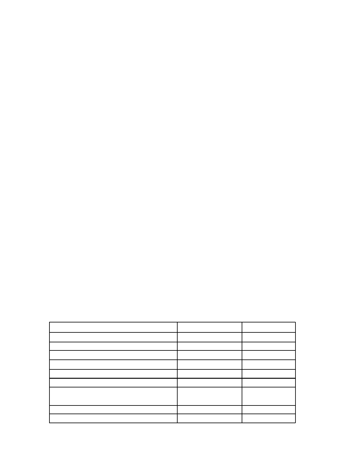
Table 1
Test/Inspection
Precap Visual Inspection
Temperature Cycle
Mechanical Shock
Hermeticity (Fine and Gross Leak)
Pre Burn-In Electrical
Burn-In (160 hours)
Final Electrical Test
Group A Testing
Final Visual Inspection
CMB
100%
100%
100%
100%
100%
100%
-55°C, +25°C,
+125°C
100%
100%
2.1 - 8
CMP
100%
N.A.
N.A.
100%
N.A.
N.A.
+25°C
N.A.
100%
Share Link: