ADMC201AP Просмотр технического описания (PDF) - Analog Devices
Номер в каталоге
Компоненты Описание
производитель
ADMC201AP Datasheet PDF : 15 Pages
| |||
ADMC201
INTERRUPT GENERATION
There are three interrupt sources on the ADMC201 that may be
independently enabled to generate interrupts. The first inter-
rupt source is the Analog Input Block, which, if enabled,
generates an interrupt at the end of conversion. The second in-
terrupt source is the Vector Transformation Block, which, if
enabled, generates an interrupt at the end of a Vector Transfor-
mation. The third interrupt source is the Digital I/O Block.
Each digital I/O bit, if configured for input and enabled, gener-
ates an interrupt when its input level changes.
When a 1 is stored in Bit 7 of the SYSCTRL register, ADC in-
terrupts are enabled. When a 1 is stored in Bit 6 of the
SYSCTRL register, Vector Transformation interrupts are en-
abled. When a 1 is stored in any of Bits 6–11 of the PIOCTRL
register, digital I/O change of state interrupts are enabled for
Bits 0–5 respectively. Upon a reset of the chip, all bits are set to
the default condition, 0, thus disabling all interrupts.
When an enabled interrupt occurs, Bit 11 of the SYSSTAT reg-
ister becomes a 1. If that interrupt had been an ADC interrupt,
Bit 0 of SYSSTAT register would also be set to 1. If that inter-
rupt had been a Vector Transformation interrupt, Bit 1 of
SYSSTAT would be set to 1. If that interrupt had been a digi-
tal I/O interrupt, then Bit 2 of the SYSSTAT would be set to 1.
Whenever the SYSSTAT register is read, these four bits go back
to their default state, 0, immediately after their values are loaded
onto the data bus. Upon a reset, these four bits also go to their
default state, 0.
The IRQ pin has an open-drain driver, which will drive it low at
the appropriate times, but the user must supply an external pull-
up resistor to bring the node back high when it is not being
pulled low.
The IRQ pin operates in one of two modes, edge mode or level
mode. In edge mode, when an enabled interrupt occurs, the
IRQ pin will be driven low for one system clock period. In level
mode, when an enable interrupt occurs, the IRQ pin will be
driven low, and will remain low until the SYSSTAT register is
read. The combination of level mode and the open-drain driver
allows multiple interrupt sources in an application to drive a
single interrupt input line on the host DSP or microprocessor.
Edge mode or level mode is determined with Bit 8 of the
SYSCTRL register. Edge mode (0) is the default; a 1 in this bit
will put the IRQ pin into level mode.
The recommended method of using the interrupt generation ca-
pability is to set edge or level mode, enable the appropriate
interrupts, and then monitor the IRQ line. After the IRQ pin
goes low, the SYSSTAT register of the ADMC201 should be
read, (1) to determine if it was this chip that caused the inter-
rupt, if other lines are wired together with this IRQ pin, and
(2) if it was this chip, to determine if it was generated by the
Analog Input, Digital I/O and/or the Vector Transformation
Blocks. Once this is done, the appropriate interrupt handling
routine may be executed.
APPLICATION NOTE LIST
1. AN-407 AC Motor Control Experiments Using the ADMC200
Evaluation Board
2. AN-408 AC Motor Control Using the ADMC200 Motion
Coprocessor
3. AN-409 Advanced Motor Control Techniques Using the
ADMC200 Motion Coprocessor
POWER SUPPLY CONNECTIONS AND SETUP
The nominal positive power supply level (VDD) is +5 V ± 5%.
The Positive Power supply VDD should be connected to all
ADMC201 VDD pins (10, 19, 26, 39, 44, 59). The SGND pin
(32) and both AGND pins (27, 28) should be star point con-
nected at a point close to the AGND pins of the ADMC201.
The DGND pins (20, 40, 41, 42, 43, 46, 56, 57, 58) should
also be connected to AGND pins close to the ADMC201.
Power supplies should be decoupled at the power pins using a
0.1 µF capacitor. A 220 nF capacitor must also be connected as
close as possible between REFIN (Pin 33) and SGND (Pin 32).
In addition, the IRQ requires a 15K pull-up to the VDD supply.
SYSTEM CLOCK FREQUENCY
The nominal range of the input clock for the ADMC201 is
6.25 MHz to 25 MHz. The external CLK frequency can be in-
ternally divided down by 2 by writing to Bit 5 of the SYSCTRL
register. If the external CLK is faster than 12.5 MHz then it is
necessary to internally divide it down.
DSP/CONTROLLER INTERFACE
The ADMC201 has a 12-bit bidirectional parallel port for inter-
facing with Analog Devices’ ADSP-2100 DSP family or
microcontrollers/microprocessors.
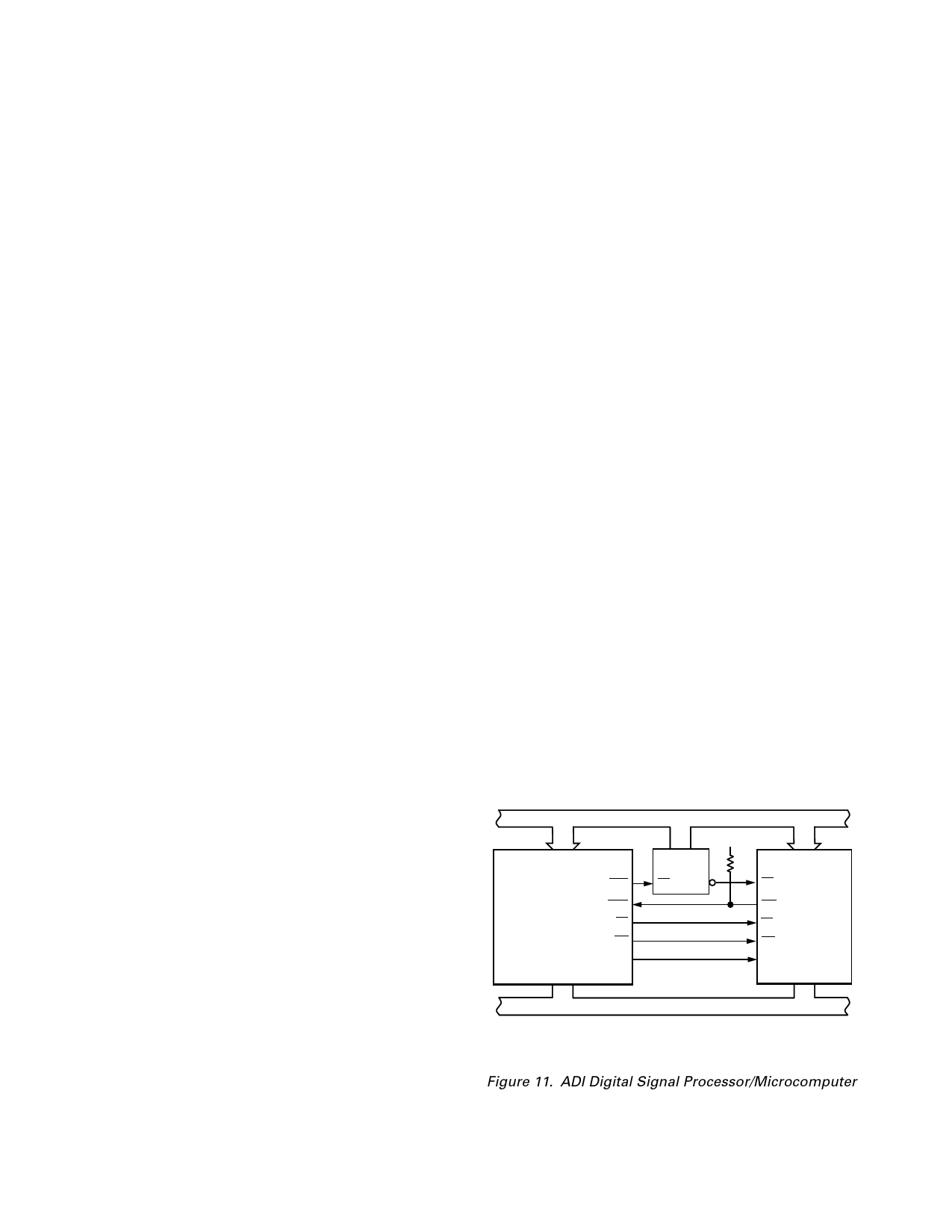
The ADMC201 coprocessor is designed to be conveniently in-
terfaced to the ADI’s family of Fixed-Point DSPs. Figures 11
and 12 show the interfacing between the ADMC201 and the
ADSP-2101/2105/2115, ADSP-2171, ADSP-2181, TMS320C2x
DSPs. In the case of the TMS320C2x, some glue logic is re-
quired to decode the RD/WR lines and invert the CLKOUT1
signal.
The ADSP-2101/2105/2115 CLKOUT frequency equals the
crystal/clock frequency of its CLKIN. This signal (CLKOUT)
can be used to directly drive the CLK line (Pin 21) on the
ADMC201. The ADMC201 coprocessor can be operated with
a clock frequency between the of 6.25 MHz and 25 MHz. If the
clock frequencies is greater than 12.5 MHz, then it is necessary
to internally divide down the external clock to derive the
ADMC201’s system clock (via SYSCTRL register).
A0–A13
ADSP-2101/
DMS
ADSP-2105/
ADSP-2115–20MHz IRQ2
ADSP-2171–10MHz RD
ADSP-2181–10MHz WR
CLKOUT
D0–D23
ADDRESS BUS
VDD
ADDRESS
DECODE
EN
A0–A3
CS
IRQ
ADMC201
RD
WR
CLK
D0–D11*
DATA BUS
*NOTE:
BY MAPPING THE ADMC201 DATA BUS TO THE TWELVE HIGHEST BITS
OF THE ADSP DATA BUS, FULL-SCALE OUTPUTS FROM THE ADC
CAN BE REPRESENTED BY ؎ 1.0 IN FIXED POINT ARITHMETIC.
Figure 11. ADI Digital Signal Processor/Microcomputer
–10–
REV. B
Share Link: 