IRFBC40 –Я—А–Њ—Б–Љ–Њ—В—А —В–µ—Е–љ–Є—З–µ—Б–Ї–Њ–≥–Њ –Њ–њ–Є—Б–∞–љ–Є—П (PDF) - International Rectifier
–Э–Њ–Љ–µ—А –≤ –Ї–∞—В–∞–ї–Њ–≥–µ
–Ъ–Њ–Љ–њ–Њ–љ–µ–љ—В—Л –Ю–њ–Є—Б–∞–љ–Є–µ
–њ—А–Њ–Є–Ј–≤–Њ–і–Є—В–µ–ї—М
IRFBC40 Datasheet PDF : 8 Pages
| |||
IRFBC40A
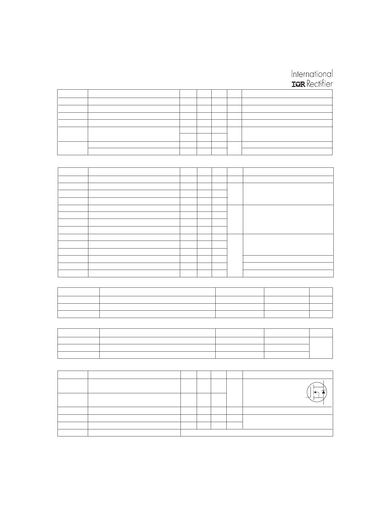
Static @ TJ = 25°C (unless otherwise specified)
Parameter
Min. Typ. Max. Units
Conditions
V(BR)DSS Drain-to-Source Breakdown Voltage 600
вИЖV(BR)DSS/вИЖTJ Breakdown Voltage Temp. Coefficient вАУвАУвАУ
RDS(on)
Static Drain-to-Source On-Resistance вАУвАУвАУ
VGS(th)
Gate Threshold Voltage
2.0
вАУвАУвАУ
IDSS
Drain-to-Source Leakage Current
вАУвАУвАУ
Gate-to-Source Forward Leakage
вАУвАУвАУ
IGSS
Gate-to-Source Reverse Leakage
вАУвАУвАУ
вАУвАУвАУ вАУвАУвАУ
0.66 вАУвАУвАУ
вАУвАУвАУ 1.2
вАУвАУвАУ 4.0
вАУвАУвАУ 25
вАУвАУвАУ 250
вАУвАУвАУ 100
вАУвАУвАУ -100
V
V/°C
вД
V
µA
nA
VGS = 0V, ID = 250µA
Reference to 25¬∞C, ID = 1mA¬Ж
VGS = 10V, ID = 3.7A ¬Д
VDS = VGS, ID = 250µA
VDS = 600V, VGS = 0V
VDS = 480V, VGS = 0V, TJ = 125°C
VGS = 30V
VGS = -30V
Dynamic @ TJ = 25°C (unless otherwise specified)
Parameter
gfs
Forward Transconductance
Qg
Total Gate Charge
Qgs
Gate-to-Source Charge
Qgd
Gate-to-Drain ("Miller") Charge
td(on)
Turn-On Delay Time
tr
Rise Time
td(off)
Turn-Off Delay Time
tf
Fall Time
Ciss
Input Capacitance
Coss
Output Capacitance
Crss
Reverse Transfer Capacitance
Coss
Output Capacitance
Coss
Output Capacitance
Coss eff. Effective Output Capacitance
Avalanche Characteristics
Min. Typ. Max. Units
Conditions
3.4 вАУвАУвАУ вАУвАУвАУ S VDS = 50V, ID = 3.7A
вАУвАУвАУ вАУвАУвАУ 42
вАУвАУвАУ вАУвАУвАУ 10
вАУвАУвАУ вАУвАУвАУ 20
вАУвАУвАУ 13 вАУвАУвАУ
ID = 6.2A
nC VDS = 480V
VGS = 10V, See Fig. 6 and 13 ¬Д
VDD = 300V
вАУвАУвАУ 23 вАУвАУвАУ ns ID = 6.2A
вАУвАУвАУ 31 вАУвАУвАУ
RG = 9.1вД
вАУвАУвАУ 18 вАУвАУвАУ
RD = 47вД¶,See Fig. 10 ¬Д
вАУвАУвАУ 1036 вАУвАУвАУ
VGS = 0V
вАУвАУвАУ 136 вАУвАУвАУ
VDS = 25V
вАУвАУвАУ 7.0 вАУвАУвАУ pF ∆Т = 1.0MHz, See Fig. 5
вАУвАУвАУ 1487 вАУвАУвАУ
вАУвАУвАУ 36 вАУвАУвАУ
вАУвАУвАУ 48 вАУвАУвАУ
VGS = 0V, VDS = 1.0V, ∆Т = 1.0MHz
VGS = 0V, VDS = 480V, ∆Т = 1.0MHz
VGS = 0V, VDS = 0V to 480V ¬Е
Parameter
EAS
Single Pulse Avalanche Energy¬В
IAR
Avalanche Current¬Б
EAR
Repetitive Avalanche Energy¬Б
Thermal Resistance
Typ.
вАУвАУвАУ
вАУвАУвАУ
вАУвАУвАУ
Max.
570
6.2
13
Units
mJ
A
mJ
Parameter
RќЄJC
RќЄCS
RќЄJA
Junction-to-Case
Case-to-Sink, Flat, Greased Surface
Junction-to-Ambient
Diode Characteristics
Typ.
вАУвАУвАУ
0.50
Max.
1.0
вАУвАУвАУ
62
Units
°C/W
Parameter
IS
Continuous Source Current
(Body Diode)
ISM
Pulsed Source Current
(Body Diode) ¬Б
VSD
Diode Forward Voltage
trr
Reverse Recovery Time
Qrr
Reverse RecoveryCharge
ton
Forward Turn-On Time
2
Min. Typ. Max. Units
Conditions
MOSFET symbol
D
вАУвАУвАУ вАУвАУвАУ 6.2
A showing the
integral reverse
G
вАУвАУвАУ вАУвАУвАУ 25
p-n junction diode.
S
вАУвАУвАУ вАУвАУвАУ 1.5 V TJ = 25¬∞C, IS = 6.2A, VGS = 0V ¬Д
вАУвАУвАУ 431 647 ns TJ = 25¬∞C, IF = 6.2A
вАУвАУвАУ 1.8 2.8 ¬µC di/dt = 100A/¬µs ¬Д
Intrinsic turn-on time is negligible (turn-on is dominated by LS+LD)
www.irf.com
Share Link: 