NUF2221W1 Просмотр технического описания (PDF) - ON Semiconductor
Номер в каталоге
Компоненты Описание
производитель
NUF2221W1 Datasheet PDF : 5 Pages
| |||
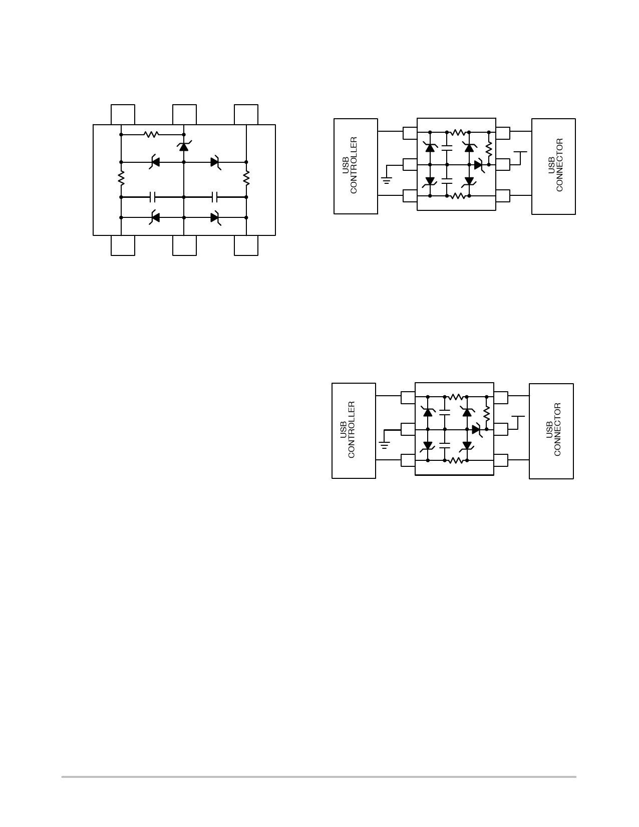
NUF2221W1
in a small and single package (SC−88, Case 419B). The
NUF2221W1 device is shown in the Figure 5.
D1(C)
6
VBUS
5
D2(C)
4
RUP
RS
C1
C1
RS
1
2
3
D1(i)
GND
D2(i)
Figure 5. Device Description
Connection for Full− Speed and Low−Speed Devices
The USB 1.1 specification calls for two data rates:
• Full−speed devices − operates in 12 Mb/s
• Low−speed devices that work in 1.5 Mb/s.
The NUF2221W1 device can be shaped for either full−speed
or low−speed by connecting one of the data lines (D+, D−)
to a 3.3 V voltage supply through the 1.5 kW pull up resistor.
The device’s connection diagrams for each speed are
described as follows:
Full−Speed Connection
The Pull up resistor (RUP) is connected to the D+ Line.
The terminal 5 is connected to a 3.3 V voltage supply while
the terminal 2 is connected to ground. The input of the D+
line is connected in the terminal 1 which outputs from the
terminal 6. Finally, the input of the D− line is connected in
the terminal 3 which outputs from the terminal 4. Figure 6
shows the connections of the NUF2221W1 device for
“Full−Speed”.
D+
1
2
0
RS
RUP
C1
C1
6
D+
3.3 V
5
D−
3
RS
4
D−
Figure 6. Full Speed Connection
Low−Speed Connection
The Pull up resistor (RUP) is connected to the D− Line.
The terminal 5 is connected to a 3.3 V voltage supply while
the terminal 2 is connected to ground. The input of the D−
line is connected in the terminal 1 which outputs from the
terminal 6. Finally, the input of the D+ line is connected in
the terminal 3 which outputs from the terminal 4. The
Figure 7 shows the connections of the NUF2221W1 device
for “Low−Speed”.
D−
1
2
0
RS
RUP
C1
C1
6
D−
3.3 V
5
D+
3
4
D+
RS
Figure 7. Low Speed Connection
http://onsemi.com
4
Share Link: 