MMDL914 Просмотр технического описания (PDF) - Willas Electronic Corp.
Номер в каталоге
Компоненты Описание
производитель
MMDL914 Datasheet PDF : 3 Pages
| |||
WILLAS
200mA Surface Mount Switching Diode - 100V
1.0A SURFACE MOUNT SCHOTTKYSBOADRR-3IE2R3 RPEaCcTkIaFgIEeRS -20V- 200V
SOD-123+ PACKAGE
FM120-M+
THRU
MMDL9F1M41200-M+
Pb Free Product
Features
• B82a0tcΩh process design, excellent power dissipation offers
Package outline
+10 V
better reverse leakage current and thermal resistance.
•
Low
2k
profile surface
mounted
applicat0io.1nµiFn
order
to
optimize bo1a00rdµsHpaceIF.
tr
tp
t
SOD-123H
IF
• Low po0w.1eµr Floss, high efficiency.
10%
• High current capability, low forward voltage drop.
0.146(3.7)
0.130(3.3)
trr
t
0.012(0.3) Typ.
• High surge capability. DUT
50 Ω• GOUuTaPrUdTring for overvoltage protection. 50 Ω INPUT
90%
•PUULlStrEa high-speed switching.
SAMPLING
GE•NESRiAliTcOoRn epitaxial planar chip, metal silOicSoCnILjLuOnScCtOioPnE.
VR
• Lead-free parts meet environmental standards of
INPUT SIGNAL
MIL-STD-19500 /228
• RoHS product for packing code suffix "G"
IR
iR(RE00..C0057)61=((111..48.))0 mA
OUTPUT PULSE
(IF = IR = 10 mA; measured
at iR(REC) = 1.0 mA)
Halogen free product for packing code suffix "H"
Mechanical dNaotteas: 1. A 2.0 kΩ variable resistor adjusted for a Forward Current (I F ) of 10mA.
• Epoxy : UL94-V0 raNteodtefsla: m2.eInrpeuttaprdualsnet is adjusted so I R(peak) is equal to 10mA.
• Case : Molded plastNico,teSsO: 3D.-t1p2»3tHrr
0.031(0.8) Typ.
,
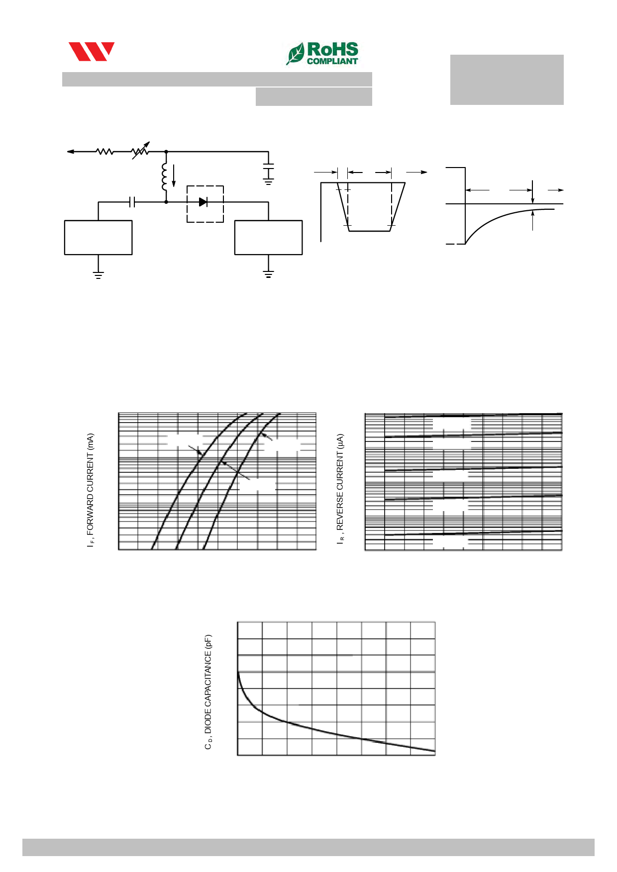
• Terminals :Plated teFrimgiunraels,1s.oRldeecraobvleepryer TMiImL-eSTEDq-u75iv0alent Test Circuit
Method 2026
0.040(1.0)
0.024(0.6)
0.031(0.8) Typ.
• Polarity : Indicated by cathode band
Dimensions in inches and (millimeters)
• Mounting Position : Any
• Weight : Approximated 0.011 gram
100
10
MAXIMUM RATINGS AND ELECTRICAL CHARACTERISTICS
T A = 150°C
Ratings at 25℃ ambient temTpeAr=a8tu5°rCe unless otherwiseTspA =ec–i4fi0e°dC.
1.0
Single phase10half wave, 60Hz, resistive of inductive load.
T A = 125°C
For capacitive load, derate current by 20%
RATINGS
Marking Code
1.0
Maximum Recurrent Peak Reverse Voltage
Maximum RMS Voltage
T A = 85°C
T A =SY25M°BCOL FM120-MH FM130-MH 0F.M1 140-MH FM150-MH FM160-MH FM180-MH FM1100-MH FM1150-MH FM1200-MH
12
13
14
15
16
18
10
115 120
VRRM
20
30
40
50
6T0A = 55°C 80
100
150
200 V
0.01
VRMS
14
21
28
35
42
56
70
105
140 V
Maximum DC Blocking Voltage
VDC
20
30
40
50
60
80
100
150
200 V
T A = 25°C
Maximum Ave0r.a1ge Forward Rectified Current
IO
0.001
1.0
A
0.2
0.4
0.6
0.8
1.0
1.2
0
10
20
30
40
50
Peak Forward Surge Current V8.3F ,mFsOsiRngWleAhRaDlf sVinOe-LwTaAvGe E (IVFOSMLTS)
superimposed on rated load (JFEDigEuC rmeeth2o.d)Forward Voltage
Typical Thermal Resistance (Note 2)
RΘJA
V R , REVER3S0E VOLTAGE (VOLTS)
A
Figure 3.40Leakage Current
℃
Typical Junction Capacitance (Note 1)
CJ
120
Operating Temperature Range
0.68
TJ
-55 to +125
-55 to +150
Storage Temperature Range
TSTG
- 65 to +175
CHARACTERISTICS
0.64
Maximum Forward Voltage at 1.0A DC
Maximum Average Reverse Current at @T A=25℃
0.60
Rated DC Blocking Voltage
@T A=125℃
SYMBOL FM120-MH FM130-MH FM140-MH FM150-MH FM160-MH FM180-MH FM1100-MH FM1150-MH FM1200-MH U
VF
0.50
0.70
0.85
0.9
0.92 V
IR
0.5
m
10
NOTES:
1- Measured at 1 MHZ and applied reverse voltage 0o.f564.0 VDC.
2- Thermal Resistance From Junction to Ambient
0.52
0
0.2
0.4
0.6
0.8
V R , REVERSE VOLTAGE (VOLTS)
Figure 4. Capacitance
2012-06
2012-1
WILLAS ELECTRONIC CORP
WILLAS ELECTRONIC CORP.
Share Link: 