HEF4020B Просмотр технического описания (PDF) - NXP Semiconductors.
Номер в каталоге
Компоненты Описание
производитель
HEF4020B Datasheet PDF : 13 Pages
| |||
NXP Semiconductors
HEF4020B
14-stage binary counter
Table 8. Dynamic power dissipation PD
PD can be calculated from the formulas shown. VSS = 0 V; tr = tf ≤ 20 ns; Tamb = 25 °C.
Symbol Parameter
VDD
Typical formula for PD (µW)
where:
PD
dynamic power 5 V
PD = 600 × fi + Σ(fo × CL) × VDD2
fi = input frequency in MHz,
dissipation
10 V
PD = 2800 × fi + Σ(fo × CL) × VDD2
fo = output frequency in MHz,
15 V
PD = 8200 × fi + Σ(fo × CL) × VDD2
CL = output load capacitance in pF,
VDD = supply voltage in V,
Σ(CL × fo) = sum of the outputs.
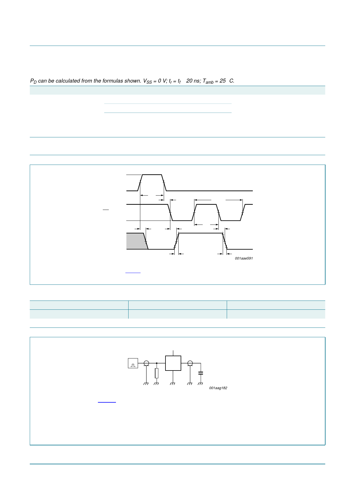
12. Waveforms
VI
MR INPUT
VSS
VI
CP INPUT
VSS
tPHL
VOH
Q0 or Qn
OUTPUT
VOL
VM
tW
VM
trec
VM
tPLH
1/fmax
tW
tPHL
tt
tt
001aae591
Measurement points are given in Table 9.
Fig 7. Propagation delays, minimum pulse widths, transition and recovery times and maximum clock frequency
Table 9. Measurement points
Supply voltage
VDD
5 V to 15 V
Input
VM
0.5VDD
Output
VM
0.5VDD
VDD
VI
G
VO
DUT
RT
CL
001aag182
Fig 8.
Test data is given in Table 10.
Definitions for test circuit:
DUT = Device Under Test.
CL = load capacitance including jig and probe capacitance.
RT = termination resistance should be equal to the output impedance Zo of the pulse generator.
Test circuit
HEF4020B_4
Product data sheet
Rev. 04 — 4 December 2008
© NXP B.V. 2008. All rights reserved.
7 of 13
Share Link: 