NE555 Просмотр технического описания (PDF) - Fairchild Semiconductor
Номер в каталоге
Компоненты Описание
производитель
NE555 Datasheet PDF : 14 Pages
| |||
VC1(t)
=
23-- VCC
=
VCC
1
–
2--
3
-–
e
(---R-----A-----+---t--HR----B-----)--C-----1--
tH = C1(RA + RB)In2 = 0.693(RA + RB)C1
(4)
(5)
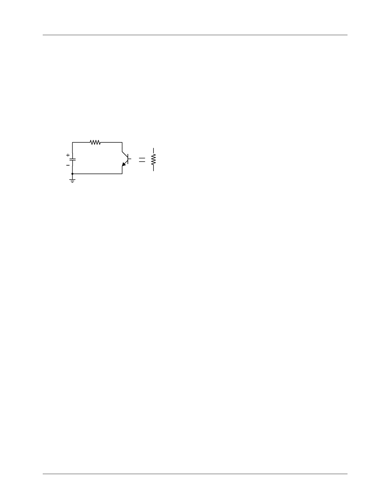
The equivalent circuit for discharging capacitor C1, when timer output is low is, as follows:
RB
C1 VC1(0-)=2Vcc/3
RD
LM555/NE555/SA555
C1
d----v---C-----1--
dt
+
-----------1-----------
RA + RB
VC1
=
0
(6)
VC1(t)
=
2--
3
V
C
Ce
-
------------------t------------------
(RA + RD)C1
(7)
Since the duration of the timer output low state(tL) is the amount of time it takes for the VC1(t) to reach Vcc/3,
1--
3
VC
C
=
2--
3
VCCe
-
----------------t--L------------------
(RA + RD)C1
(8)
tL = C1(RB + RD)In2 = 0.693(RB + RD)C1
(9)
Since RD is normally RB>>RD although related to the size of discharging Tr.,
tL=0.693RBC1
(10)
Consequently, if the timer operates in astable, the period is the same with
'T=tH+tL=0.693(RA+RB)C1+0.693RBC1=0.693(RA+2RB)C1' because the period is the sum of the charge time and discharge
time. And since frequency is the reciprocal of the period, the following applies.
frequency,
f
=
-1--
T
=
(---R-----A-----+--1---2.--4--R-4---B-----)--C-----1-
(11)
3. Frequency divider
By adjusting the length of the timing cycle, the basic circuit of Figure 1 can be made to operate as a frequency divider. Figure
8. illustrates a divide-by-three circuit that makes use of the fact that retriggering cannot occur during the timing cycle.
7
Share Link: 