DJLXT908LC Просмотр технического описания (PDF) - Intel
Номер в каталоге
Компоненты Описание
производитель
DJLXT908LC Datasheet PDF : 44 Pages
| |||
Universal 3.3V 10BASE-T and AUI Transceiver — LXT908
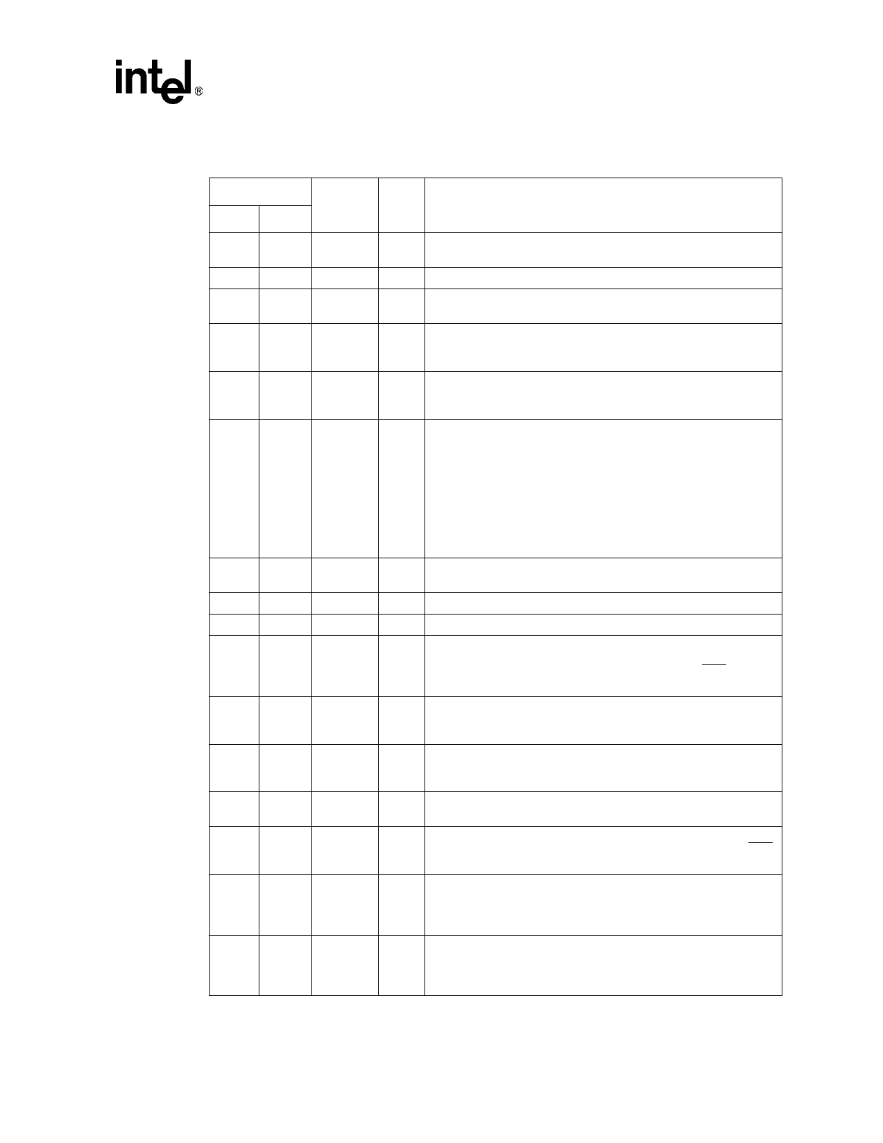
Table 1. LXT908 Signal Descriptions
Pin#
Symbol I/O
PLCC LQFP
Description
1
10
VCC1
– Power 1 and 2. Connect to positive power supply terminal (+3.3V
34
56
VCC2
– DC).
–
9
VCCA
– Analog Supply. (+3.3V)
2
11
CIP
I AUI Collision Pair. Differential input pair connected to the AUI
3
12
CIN
I transceiver CI circuit. The input is collision signaling or SQE.
Normal Threshold. When NTH is High, the normal TP squelch
4
13
NTH
I threshold is in effect. When NTH is Low, the normal TP squelch
threshold is reduced by 4.5 dB.
5
14
6
15
25
44
MD0
MD1
MD2
I Mode Select 0 (MD0), Mode Select 1 (MD1) and Mode Select 2
I (MD2). Mode select pins determine the controller compatibility
I mode as specified in Table 2 on page 12.
1, 2, 6,
16, 17,
18, 20,
30, 31,
7, 29
32, 33,
41, 43,
N/C
48, 49,
50, 51,
60, 63,
64
– No Connect. These pins may be left unconnected or tied to ground.
8
19
LI
I
Link Test Enable. Controls Link Integrity Test; enabled when High,
disabled when Low.
9
21
JAB
O Jabber Indicator. Output goes High to indicate Jabber state.
10
22
TEST
I Test. This pin must be tied High.
Transmit Clock. A 10 MHz clock output. This clock signal should
11
23
TCLK
O
be directly connected to the transmit clock input of the controller.
TCLK goes to high impedance (tri-state) when LEDT/PDN is pulled
Low externally.
12
24
TXD
Transmit Data. Input signal containing NRZ data to be transmitted
I on the network. TXD is connected directly to the transmit data
output of the controller.
13
25
TEN
Transmit Enable. Enables data transmission and starts the Watch-
I Dog Timer. Synchronous to TCLK (see Test Specifications for
details).
14
26
CLKO
O Crystal Oscillator. A 20 MHz crystal must be connected across
15
27
CLKI
I these pins, or a 20 MHz clock applied at CLKI, with CLKO left open.
16
28
COL
Collision Detect. Output driving the collision detect input of the
O controller. COL goes to high impedance (tri-state) when LEDT/PDN
is pulled Low externally.
Automatic Port Select. When High, automatic port selection is
17
29
AUTOSEL
I
enabled (the LXT908 defaults to the AUI port only if TP link
integrity = Fail). When Low, manual port selection is enabled (the
PAUI pin determines the active port).
Receive LED. Open drain driver for the receive indicator LED.
18
34
LEDR
O
Output is pulled Low during receive, except when data is being
looped back to DIN/DIP from a remote transceiver (external MAU).
LED “On” time (Low output) is extended by approximately 100 ms.
Datasheet
9
Document #: 249049
Revision #: 002
Rev. Date: June 19, 2001
Share Link: 