M52759SP Просмотр технического описания (PDF) - Vishay Siliconix
Номер в каталоге
Компоненты Описание
производитель
M52759SP Datasheet PDF : 27 Pages
| |||
M52759SP
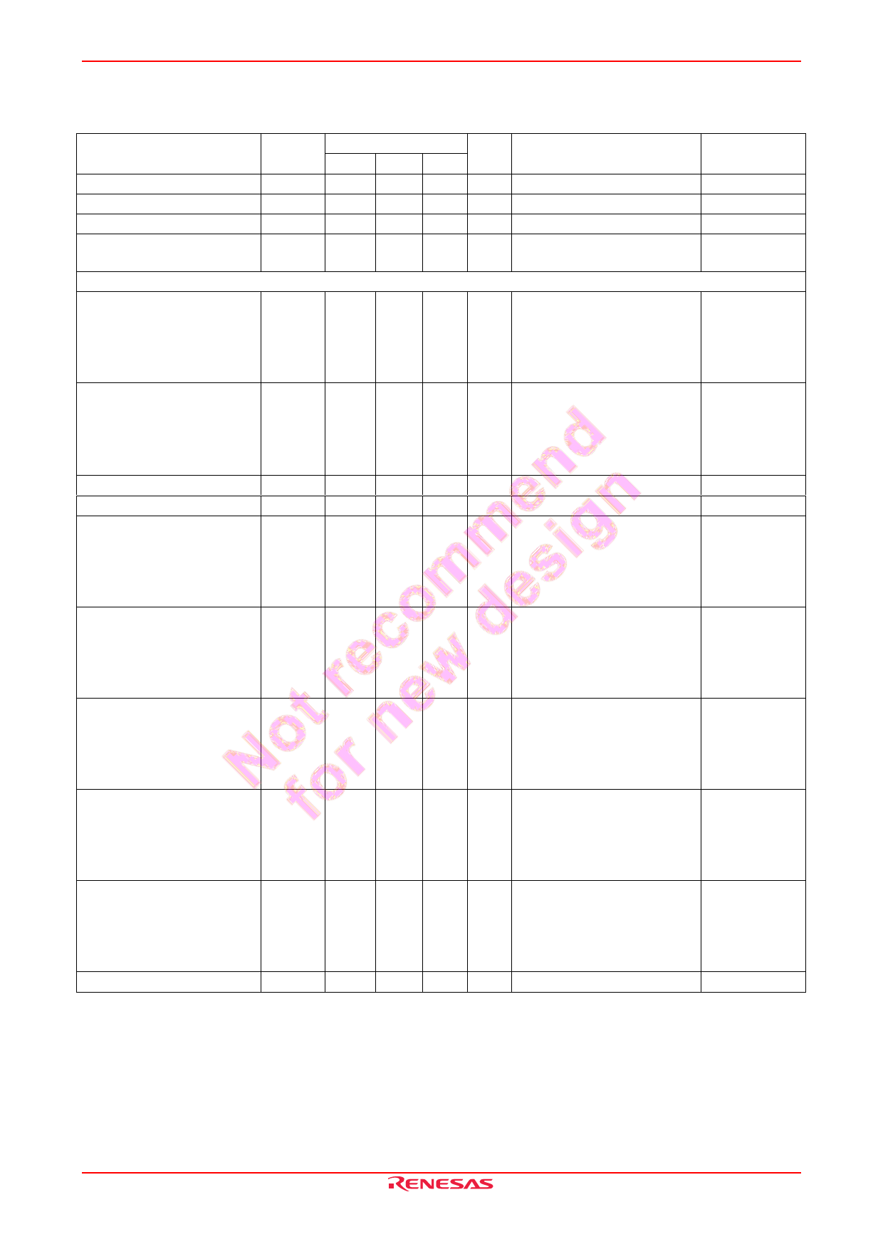
Electrical Characteristics
Item
Circuit current 1
Circuit current 2
Reference voltage output
Reference voltage
temperature drift
Horizontal Block
H-pulse low input range
H-pulse high input range
H-pulse low input current
H-pulse high input current
H parabola width
H parabola delay 1
H parabola delay 2
H parabola delay 3
Delay temperature drift
Pin 15 input current
Symbol
ICCH
ICCV
VREF
DREF
(Ta = 25°C, VCC = 12 V, unless otherwise noted)
Limits
Min. Typ. Max. Unit
Test Conditions
Pin No.
15.1 21.5 27.9 mA (10) Measure
10
5.2 7.4 9.6 mA (20) Measure
20
6.75 6.95 7.15 V (14) Measure
14
49
ppm/ (14) Measure
14
deg
VIL
0.0 2.0 V (6) 2.4 V in
7
(7) Measure
(15) 3.0 V in
(17) fH = 96 kHz H-pulse in
(19) 6.1 V in
VIH
3.0
VCC V (6) 2.4 V in
7
−2.0
(7) Measure
(15) 3.0 V in
(17) fH = 96 kHz H-pulse in
(19) 6.1 V in
IIL
−5.0 −0.6 −0.1 µA (17) 0 V in, measure
17
IIH
−1.0 0.0 1.0 µA (17) 5 V in, measure
17
TW
0.6 0.8 1.0 µs (6) 2.4 V in
7
(7) Measure
(15) 3.0 V in
(17) fH = 96 kHz H-pulse in
(19) 6.1 V in
TD1
0.1 0.3 0.5 µs (6) 2.4 V in
7
(7) Measure
(15) 0 V in
(17) fH = 96 kHz H-pulse in
(19) 6.1 V in
TD2
0.4 0.6 0.8 µs (6) 2.4 V in
7
(7) Measure
(15) 1.3 V in
(17) fH = 96 kHz H-pulse in
(19) 6.1 V in
TD3
2.9 3.1 3.3 µs (6) 2.4 V in
7
(7) Measure
(15) 4.0 V in
(17) fH = 96 kHz H-pulse in
(19) 6.1 V in
DD
0.08 ns/ (6) 2.4 V in
7
deg (7) Measure
(15) 3.0 V in
(17) fH = 96 kHz H-pulse in
(19) 6.1 V in
I15
−5.0 −0.3 −0.1 µA (17) 2.5 V in, measure
15
REJ03F0197-0201 Rev.2.01 Mar 31, 2008
Page 4 of 26
Share Link: 