1N5818-E3(2007) Просмотр технического описания (PDF) - Vishay Semiconductors
Номер в каталоге
Компоненты Описание
производитель
1N5818-E3 Datasheet PDF : 5 Pages
| |||
1N5817 thru 1N5819
Vishay General Semiconductor
ELECTRICAL CHARACTERISTICS (TA = 25 °C unless otherwise noted)
PARAMETER
TEST CONDITIONS SYMBOL 1N5817
Maximum instantaneous forward voltage (1) 1.0
Maximum instantaneous forward voltage (1) 3.1
VF
0.450
VF
0.750
Maximum average reverse current at rated
DC blocking voltage (1)
TA = 25 °C
TA = 100 °C
IR
Typical junction capacitance
4.0 V, 1.0 MHz
CJ
125
Note:
(1) Pulse test: 300 µs pulse width, 1 % duty cycle
1N5818
1N5819
0.550
0.600
0.875
0.900
1.0
10
110
UNIT
V
V
mA
pF
THERMAL CHARACTERISTICS (TA = 25 °C unless otherwise noted)
PARAMETER
SYMBOL 1N5817
1N5818
1N5819
UNIT
Typical thermal resistance (1)
RθJA
RθJL
50
15
°C/W
Note:
(1) Thermal resistance from junction to lead vertical P.C.B. mounted, 0.375" (9.5 mm) lead length with 1.5 x 1.5" (38 x 38 mm) copper pads
ORDERING INFORMATION (Example)
PREFERRED P/N
UNIT WEIGHT (g) PREFERRED PACKAGE CODE
1N5819-E3/54
0.332
54
1N5819-E3/73
0.332
73
BASE QUANTITY
5500
3000
DELIVERY MODE
13" diameter paper tape and reel
Ammo pack packaging
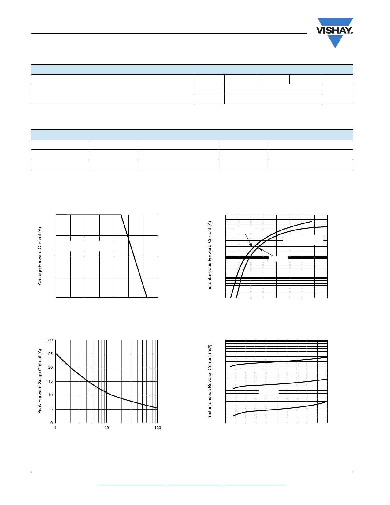
RATINGS AND CHARACTERISTICS CURVES
(TA = 25 °C unless otherwise noted)
1.0
0.75
Resistive or Inductive Load
0.375" (9.5 mm) Lead Length
0.5
0.25
0
0
20 40 60 80 100 120 140
Case Temperature (°C)
Figure 1. Forward Current Derating Curve
30
25
20
15
10
5
0
1
10
100
Number of Cycles at 60 Hz
Figure 2. Maximum Non-Repetitive Peak Forward Surge Current
www.vishay.com
44
For technical questions within your region, please contact one of the following: Document Number: 88525
PDD-Americas@vishay.com, PDD-Asia@vishay.com, PDD-Europe@vishay.com
Revision: 20-Aug-07
Share Link: 