MAP3202 Просмотр технического описания (PDF) - MagnaChip Semiconductor
Номер в каталоге
Компоненты Описание
производитель
MAP3202 Datasheet PDF : 15 Pages
| |||
Confidential
Datasheet Version 1.1
SCP Circuit uses very fast comparator in order to turn off
MOSFET when the abnormal condition of SCP Level is
detected. Because high current can be driven into channel of
MOSFET when LED string is shorted.
5. Auto-Restart Protection
The MAP3202 offers Auto Restart protection function which is
recovered into normal operation mode when protection
condition is cleared. The auto restart time (TAR) is fixed at 1mS,
Fosc = 100KHz. it is recovered to normal operating mode if
SCP or OVP condition is cleared.
Dimming Control
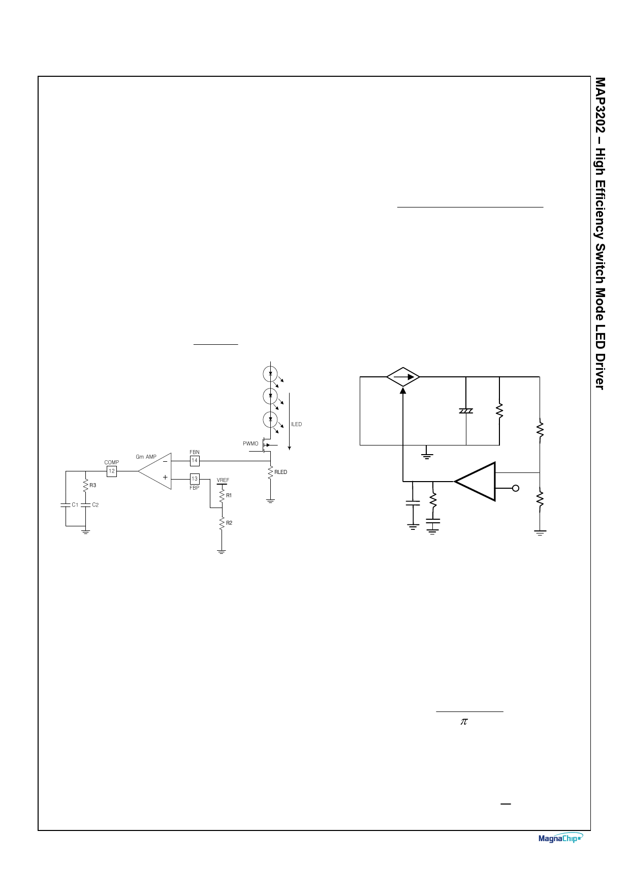
1. LED Current
The MAP3202 decides LED Current setting by the value of
RLED resistance and voltage on FBP pin as below
LED _ Current = V _ FBP
RLED
The MAP3202 was designed for DCM operation.
In CCM operation, sub-harmonic oscillation may occur if duty
cycle exceeds over 50%. Because there is no slope
compensation functions.
The following is the equation to calculate max value of Inductor
in DCM operation.
L(max)
=
[(1 −
D)2
* D * RO(max)
2
*Ts(min) ]
Where,
R0(max) = Maximum output impedance
TS(min) = Minimum Switching Period
Closed Loop Network Selection
The MAP3202 controls in peak current mode. Current mode
easily achieves compensation by consisting simple single Pole
from Double Pole that LC filer makes at Voltage mode
Vout
Vc ~~ iL
Co Ro
Figure 7 LED Current Setting
2. PWM Dimming
The MAP3202 makes same phase PWMO output from logic
PWM signal of PWMI using internal Level shift. PWMO of
operating voltage level is between GND and VCC.
Inductor Selection
Inductor value should be decided before system design.
Because the selection of the inductor affects the operating
mode of CCM (Continuous current mode) or DCM
(Discontinuous current mode), In CCM operation, inductor size
should be bigger, even though the ripple current and peak
current of inductor can be small.
In DCM operation, even ripple current and peak current of
inductor should be large while the inductor size can be smaller
so that it is more effective in BLU of TV and Notebook
application.
March 2012
(Optional)
Vc
-
++
Rc
Vref
Cc
Figure 8 Current mode Loop Compensation
1. Select fC (Crossover frequency)
In general, crossover frequency is selected from 1/3 ~ 1/6
range of the switching frequency. If fc is large, there is
possibility of oscillation to occur, although time response gets
better.
On the other hand, if fc is small, time response will be bad,
while it has improved stability, which may cause over shoot or
under shoot in abnormal condition.
It should be noted that fc should be set at smaller location than
RHP Zero.
Ro * (1 − D)2
f RHP = 2π * L
2. Select fPO
f PO = fC * GO
A
( GO = DC Gain of plant =
)
B
Page 11
Share Link: 