MAP3202SIRH Просмотр технического описания (PDF) - MagnaChip Semiconductor
Номер в каталоге
Компоненты Описание
производитель
MAP3202SIRH Datasheet PDF : 15 Pages
| |||
Confidential
Datasheet Version 1.1
GATE1
CH1 Boost Drain
GATE2
CH2 Boost Drain
GATE3
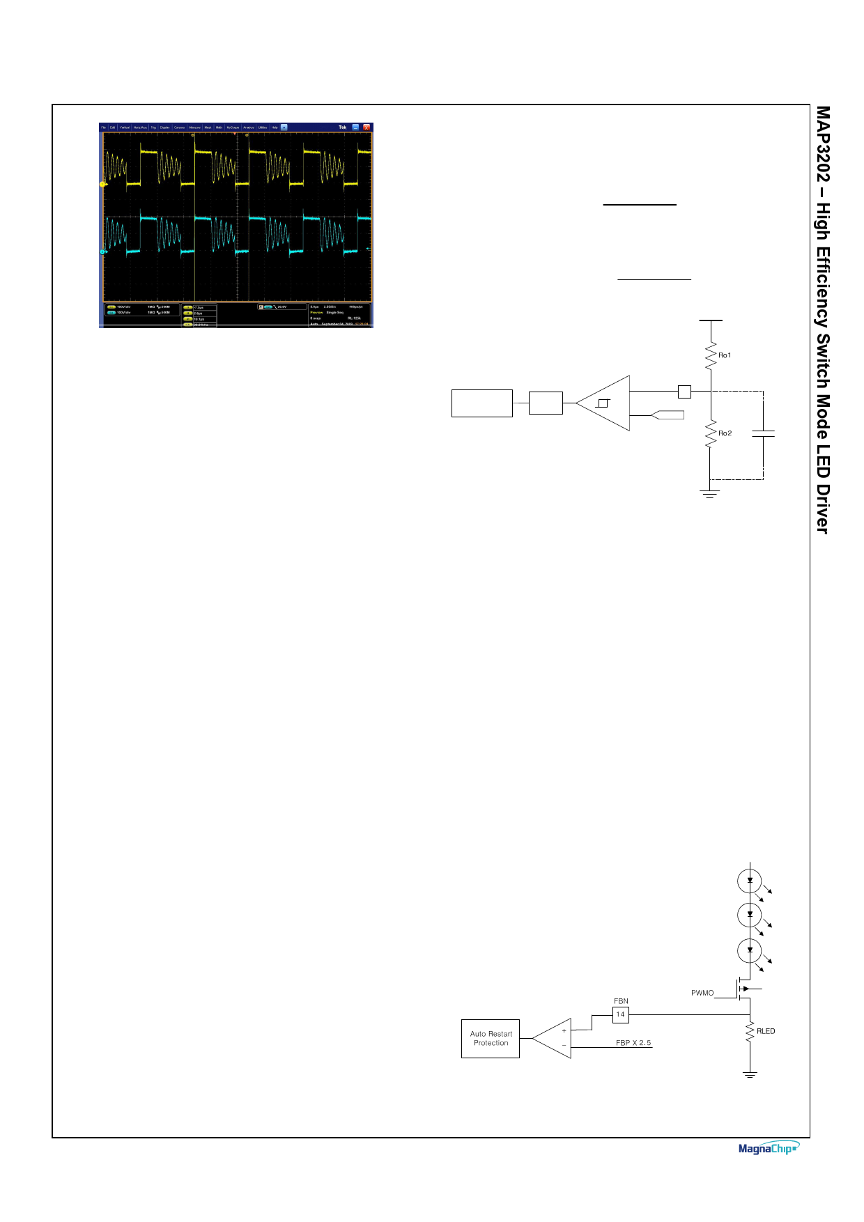
Figure 4 Peer - to -peer synchronization
(Fixed 100 KHz)
PROTECTION
The MAP3202 offers the features such as UVLO, Boost
current limit, Over Voltage Protection and Short Current
Protection of LED (SCP). OVP and SCP are operated in auto
restart protection mode.
1. Under Voltage Lock Out (UVLO)
When VCC voltage reaches over 8V, UVLO starts operating
which enables Internal 5V Regulator, making all internal control
circuits including oscillator, gate driver and protection circuit
ready for operation and output pin of GATE, PWMO and
COMP starts operating depending on the input status of PWMI.
If VCC voltage drops below 7V during normal operation, UVLO
starts operating, shutting down Internal Control Circuit and
stopping operation of GATE, PWMO and COMP. It is followed
by disabling of internal 5V regulator, and shut off of all IC
operation.
2. Maximum Boost Current Limit
MAP3202 has the internal current limit threshold voltage, 0.36V
(Typ.). If the sense voltage on CS pin exceeds 0.36V,
MAP3202 limits boost on duty every pulse.
MAP3202’s CS circuitry has the Leading edge blank time at
100nS (min.).
3. Over Voltage Protection (OVP)
The MAP3202 offers over voltage protection in order to protect
MOSFET of boost converter and external component
connected to Output pin when output voltage is in abnormal
condition.
OVP Circuit monitors whether output voltage is stable level or
not
If OVP Pin voltage reaches threshold condition (3V Typ.), it can
shut off the switching of GATE and PWMO and then output
voltage is falling as much as the leakage current time. If the
voltage of OVP Pin reaches OVP falling threshold (2.7V Typ.),
IC releases protection mode. In this time, protection releasing
can be decided as value of capacitor with the longer discharge
between auto restart time and the time of leakage current
connected to output.
The over voltage protection can be decided in the following
equation.
- Protection voltage:
Ro1+ Ro2
Vout = 3* Ro2
- Protection release voltage:
Vout
=
2.7 *
Ro1+ Ro2
Ro2
Vout
OVP
Auto Restart
Protection
LPF
+
10
-
3V / 2.7V
Ca
Figure 5 Over voltage protection circuit
The MAP3202 included LPF (low pass filter) of 200nS (Typ.) in
OVP circuit for better noise immunity, It may need a high noise
margin when Ro1 and Ro2 use high resistance value in order
to minimize Power loss.
The total values of Ro1 and Ro2 need to be lower than 1Mohm.
In this case, it is recommended to add Capacitor.
4. Short Current Protection of LED (SCP)
The MAP3202 offers protection circuit to prevent short current
when LED string is shorted
In Figure 6 when LED string is shorted, the voltage of FBN Pin
can be calculated in the following equation
VFBN = I LED ∗ RLED
If the voltage of FBN pin exceeds the voltage of FBP X 2.5,
MAP3202 goes into SCP mode.
It is recommended which FBP max voltage 1.5V.
Figure 6 Short current protections
March 2012
Page 10
Share Link: 