NTE1784 Просмотр технического описания (PDF) - NTE Electronics
Номер в каталоге
Компоненты Описание
производитель
NTE1784 Datasheet PDF : 4 Pages
| |||
Electrical Characteristics (Cont’d): (TA = +25°C, VS = 12V unless otherwise specified)
Parameter
Symbol
Test Conditions
Min Typ Max
Sync Pulse–Oscillator Phase Comparator
Control Voltage Range
V13
Control Peak Range
I13
Phase Lock Loop
4.6 to 1.4
–
±2
–
–
2
–
Catching and Holding Range
f
– ±700 –
Overall Phase Relationship
Phase Relation between Middle of Flyback
to
Pulse and Middle of Sync Pulse
– 2.6 –
Adjustment Sensitivity
–
65
–
–
10
–
Unit
V
mA
kHz/µs
Hz
µs
mV/µs
µA/µs
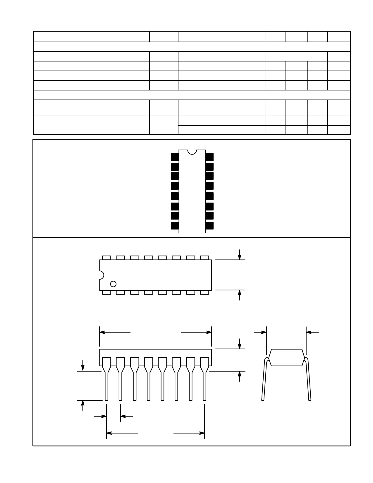
Pin Connection Diagram
VCC 1
Output (–) 2
Output (+) 3
Protection Circuit Input 4
Phase Shifter Filter 5
Flyback Input 6
Key & Blanking Pulse Output 7
Sync Separator Input 8
16 GND
15 OSC Current Control
14 OSC
13 Continuous Current Output
12 Time Constant Switch
11 Coincidence Detector
10 Vertical Sync Output
9 Vertical Sync Separator Input
16
9
.260
(6.6)
Max
1
8
.245
(6.22)
Min
.785 (19.9) Max
.100 (2.54)
.700 (17.7)
.200
5.08)
Max
.300 (7.62)
Share Link: 