AS1152 Просмотр технического описания (PDF) - austriamicrosystems AG
Номер в каталоге
Компоненты Описание
производитель
AS1152 Datasheet PDF : 15 Pages
| |||
AS1152
Data Sheet
austriamicrosystems
Switching Characteristics
Switching Characteristics
(VCC = +3.0 to +3.6V, RL = 100Ω ±1%, f ≤ 150MHz, TA = -40 to +85°C
Typical values are at VCC = +3.3V, TA = +25ºC, Unless Otherwise Noted.) 1, 2, 3
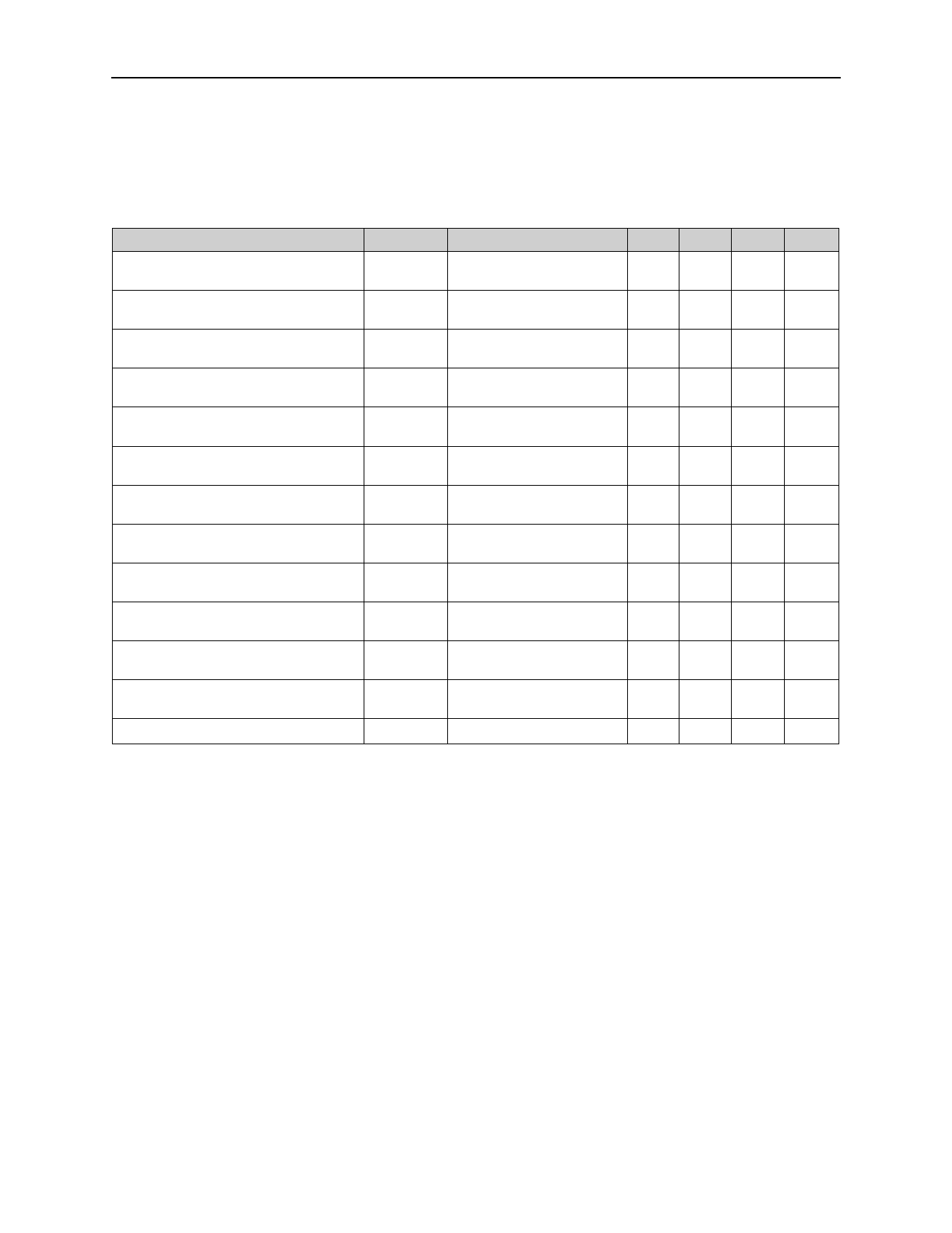
Table 3. Switching Characteristics
Parameter
Symbol
Conditions
Min Typ Max Unit
Differential Propagation Delay,
High-to-Low
tPHLD
Figure 18 on page 11 and
Figure 19 on page 11
1.1
1.7
ns
Differential Propagation Delay,
Low-to-High
tPLHD
Figure 18 on page 11 and
Figure 19 on page 11
1.1
1.7
ns
Differential Pulse Skew 4
tSKD1
Figure 18 on page 11 and
Figure 19 on page 11
0.04 0.35 ns
Differential Channel-to-Channel Skew 5 tSKD2
Figure 18 on page 11 and
Figure 19 on page 11
0.07 0.60 ns
Differential Part-to-Part Skew 6
tSKD3
Figure 18 on page 11 and
Figure 19 on page 11
0.13 0.8
ns
Differential Part-to-Part Skew 7
tSKD4
Figure 18 on page 11 and
Figure 19 on page 11
0.43 1.0
ns
Rise Time
tTLH
Figure 18 on page 11 and
Figure 19 on page 11
0.2
0.39
2.6
ns
Fall Time
tTHL
Figure 18 on page 11 and
Figure 19 on page 11
0.2
0.39
2.6
ns
Disable Time, High-to-Z
tPHZ
Figure 21 on page 12 and
Figure 22 on page 12
3
4
ns
Disable Time, Low-to-Z
tPLZ
Figure 21 on page 12 and
Figure 22 on page 12
3
4
ns
Enable Time, Z-to-High
tPZH
Figure 21 on page 12 and
Figure 22 on page 12
2
3
ns
Enable Time, Z-to-Low
tPZL
Figure 21 on page 12 and
Figure 22 on page 12
2
3
ns
Maximum Operating Frequency 8, 9
fMAX
250
MHz
Notes:
1. Parameters are guaranteed by design and characterization.
2. CL includes probe and jig capacitance.
3. Signal generator conditions for dynamic tests: VOL = 0, VOH = 3V, f = 100MHz, 50% duty cycle, RO = 50Ω,
tR ≤ 1ns, tF ≤ 1ns (0 to 100%).
4. tSKD1 is the magnitude difference of differential propagation delay. tSKD1 = |tPHLD - tPLHD|.
5. tSKD2 is the magnitude difference of tPHLD or tPLHD of one channel to the tPHLD or tPLHD of another channel on
the same device.
6. tSKD3 is the magnitude difference of any differential propagation delays between devices at the same VCC and
within 5°C of each other.
7. tSKD4 is the magnitude difference of any differential propagation delays between devices operating over the
rated supply and temperature ranges.
8. fMAX signal generator conditions: VOL = 0, VOH = 3V, 50% duty cycle, RO = 50Ω,
tR ≤ 1ns, tF ≤ 1ns (0 to 100%).
9. Conforms to ANSI TIA/EIA 644 LVDS Standards ≤150MHz. Maximum operating frequency of 250MHz is pos-
sible using an AS1150 receiver.
www.austriamicrosystems.com
Revision 1.00
4 - 15
Share Link: 