RF105 Просмотр технического описания (PDF) - Conexant Systems
Номер в каталоге
Компоненты Описание
производитель
RF105 Datasheet PDF : 12 Pages
| |||
900 MHz Digital Spread Spectrum Transceiver
RF105
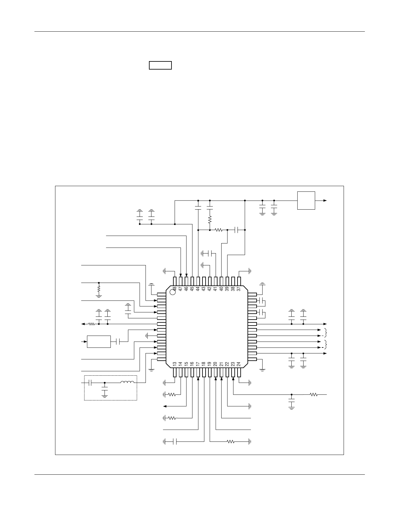
Recommendations on Layout and Implementation_____
A typical applications schematic is shown in Figure 4. All
Vcc pins should be decoupled as close to the supply pin as
possible, preferably right at the input pins.
All ground pins should have minimum trace inductance to
ground. If a ground plane cannot be provided right at the
pins, the vias to the ground plane should be placed as
close to the pins as possible. There should be one via for
each ground pin. If the ground plane is at the bottom layer,
it is recommended to have two vias in parallel for each
ground pin.
VCC1 (pin 6), VCC2 (pin 26), and VCC3 (pin 31) should be
connected to the common Vcc supply through individual
decoupling networks.
ESD Sensitivity _________________________________
The RF105 is a static-sensitive electronic device. Do not
operate or store near strong electrostatic fields. Take
proper Electrostatic Discharge (ESD) precautions.
SYNTHEN
STROBE
0.047µF
33pF
820pF
0.015µF
3920 Ω
820pF
3920 Ω
33pF
1000pF
Voltage
Regulator
VCC
0.056µF (optional)
CLK
FREF
51k Ω
DATA
1000pF
0.01µF
33pF
VCC
10Ω
TXD
TXDATA 1000pF
Shaping Filter
RXEN
LNAATTN
LNAIN
33pF *
10nH *
3.3pF *
1
2
3
4
5
6
7
8
9
10
11
12
Rmod
1.2k Ω
RFOUT
50Ω
TXEN
2200pF
* Matching network values are layout-dependent.
RF105
36
Cservo
35
0.082µF
34
Cservo
33
0.082µF
32
33pF
0.047µF
31
VCC
30
+
RXI
29
28
+
RXQ
27
26
VCC
25
33pF
0.047µF
Rgmc
875Ω
PS2
PS1
402 Ω
GC
0.056µF
Figure 4. Typical Applications Diagram – RF105
W117, Rev. B
Conexant
3
September 28, 1999
Conexant Proprietary Information
Share Link: 