PS9714 Просмотр технического описания (PDF) - California Eastern Laboratories.
Номер в каталоге
Компоненты Описание
производитель
PS9714
California Eastern Laboratories.

PS9714 Datasheet PDF : 7 Pages
| |||
PS9714
(Continued from first page.)
Notes:
1. Typical values at TA = 25°C.
2. Because VOL of 2 V or more may be output when LED current input and when output supply of VCC = 2.6 V or less, it is important to confirm
the characteristics (operation with the power supply on and off) during design, before using this device.
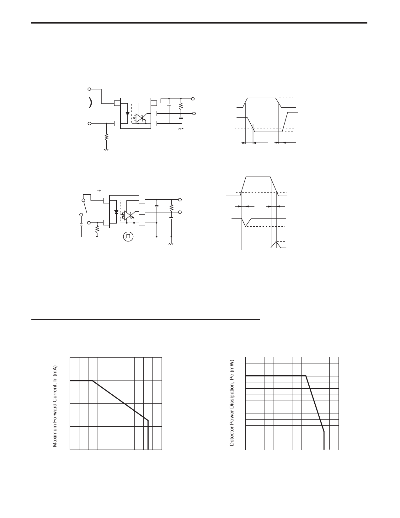
3. Test Circuit for Propagation Delay Time:
Pulse Input
(PW = 10 µs
Duty Cycle = 1/10)
Input (monitor)
47 Ω
Vcc = 5 V
0.1
µF RL = 350 Ω
VO (monitor)
CL
Input
Output
tPHL
IF = 7.5 mA
50 %
VOH
1.5 V
VOL
tPLH
*CL is approximately 15 pF which includes probe and stray wiring capacitance.
4. Test Circuit for Common Mode Transient Immunity:
GL SW IF
0.1 µF
VCM
Vcc = 5 V
RL
VO (monitor)
CL
90 %
VCM
10 %
tr
VO
(IF = 0 mA)
1 kV
0V
tf
VOH
2V
VO
(IF = 7.5 mA)
0.8 V
VOL
USAGE CAUTIONS
1. Protect against static electricity when handling this product.
2. Bypass capacitor greater than 0.1 µF is used between VCC and GND near device (lead distance: 10 mm MAX).
TYPICAL PERFORMANCE CURVES (TA = 25°C, unless otherwise specified)
MAXIMUM FORWARD CURRENT
vs. AMBIENT TEMPERATURE
40
30
20
10
0
20
40
60
80 85 100
Ambient Temperature, TA (°C)
DETECTOR POWER DISSIPATION
vs. AMBIENT TEMPERATURE
50
40
30
20
10
0
0
20
40
60
80 85
100
Ambient Temperature, TA (°C)
Share Link: