DS21554L Просмотр технического описания (PDF) - Maxim Integrated
Номер в каталоге
Компоненты Описание
производитель
DS21554L Datasheet PDF : 124 Pages
| |||
DS21354/DS21554 3.3V/5V E1 Single-Chip Transceivers
1. INTRODUCTION
The DS21354/DS21554 are superset versions of the popular DS2153 and DS2154 SCTs offering the new
features listed below. All the original features of the DS2153 and DS2154 have been retained, and the
software created for the original devices is transferable into the DS21354/DS21554.
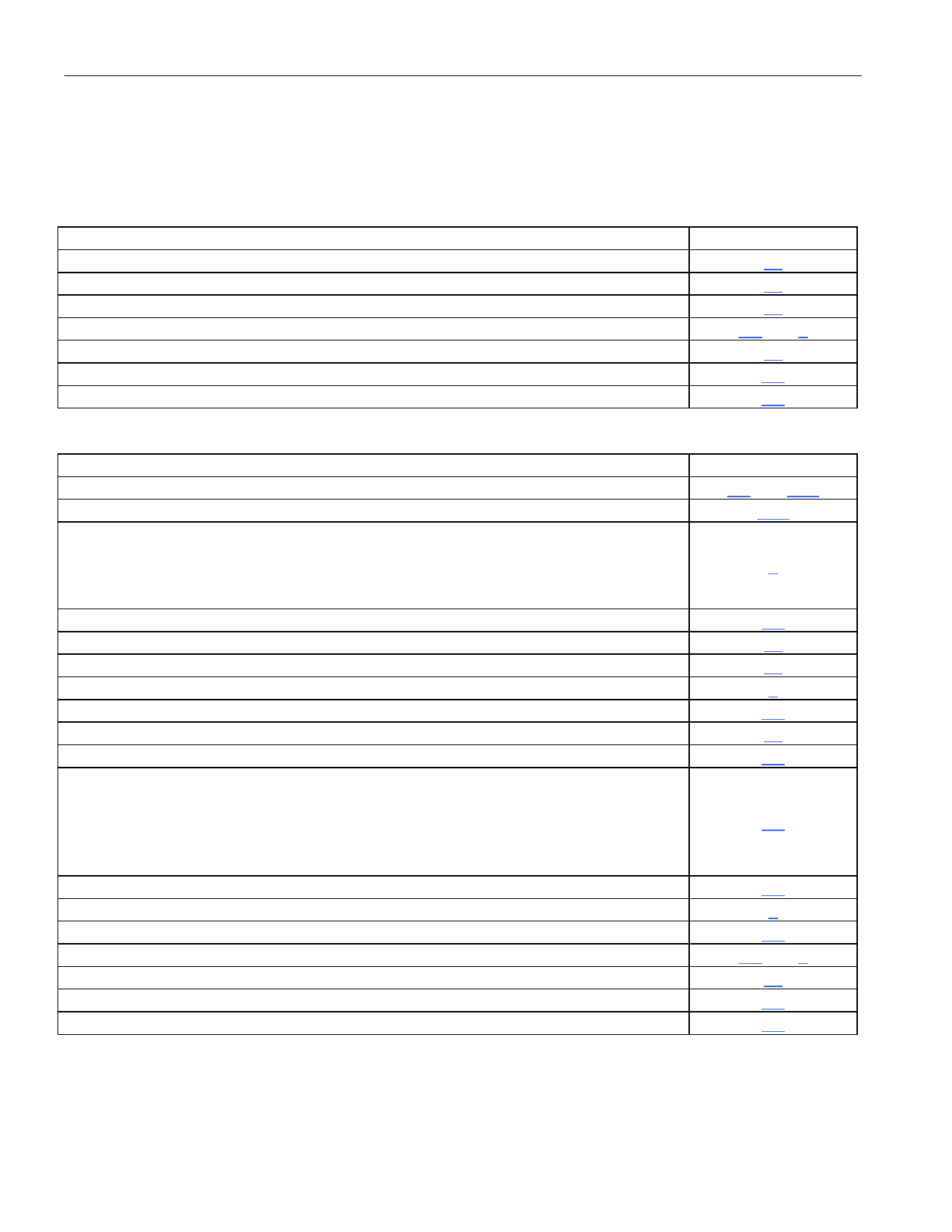
New Features in the DS21354 and DS21554
FEATURE
HDLC controller with 64-Byte Buffers for Sa Bits or DS0s or Sub DS0s
Interleaving PCM Bus Operation
IEEE 1149.1 JTAG-Boundary Scan Architecture
3.3V (DS21354 Only) Supply
Line Interface Support for the G.703 2.048 Synchronization Interface
Customer Disconnect Indication (...101010...) Generator
Open-Drain Line Driver Option
SECTION
14
17
16
1.1 and 2
15
5.6
5.6
Additional Features in the DS21354 and DS21554
FEATURE
Option for nonmultiplexed bus operation
Crystal-less jitter attenuation
Additional hardware signaling capability including:
Receive signaling reinsertion to a backplane multiframe sync
Availability of signaling in a separate PCM data stream
Signaling freezing Interrupt generated on change of signaling data
Improved receive sensitivity: 0 to -43dB
Per-channel code insertion in both transmit and receive paths
Expanded access to Sa and Si bits
RCL, RLOS, RRA, and RAIS alarms now interrupt on change of state
8.192MHz clock synthesizer
Per-channel loopback
Addition of hardware pins to indicate carrier loss and signaling freeze
Line interface function can be completely decoupled from the framer/formatter to
allow:
Interface to optical, HDSL, and other NRZ interfaces
“tap” the transmit and receive bipolar data streams for monitoring purposes
Be able to corrupt data and insert framing errors, CRC errors, etc.
Transmit and receive elastic stores now have independent backplane clocks
Ability to monitor one DS0 channel in both the transmit and receive paths
Access to the data streams in between the framer/formatter and the elastic stores
AIS generation in the line interface that is independent of loopbacks
Transmit current limiter to meet the 50mA short circuit requirement
Option to extend carrier loss criteria to a 1ms period as per ETS 300 233
Automatic RAI generation to ETS 300 011 specifications
SECTION
1.1 and 20.2
15.3
9
1.1
10
13
6
1.1
10
1.1
1.1
1.1
8
1.1
1.1 and 5
15
5.4
5.4
6 of 124
Share Link: 