LA1265 Просмотр технического описания (PDF) - SANYO -> Panasonic
Номер в каталоге
Компоненты Описание
производитель
LA1265 Datasheet PDF : 15 Pages
| |||
LA1265
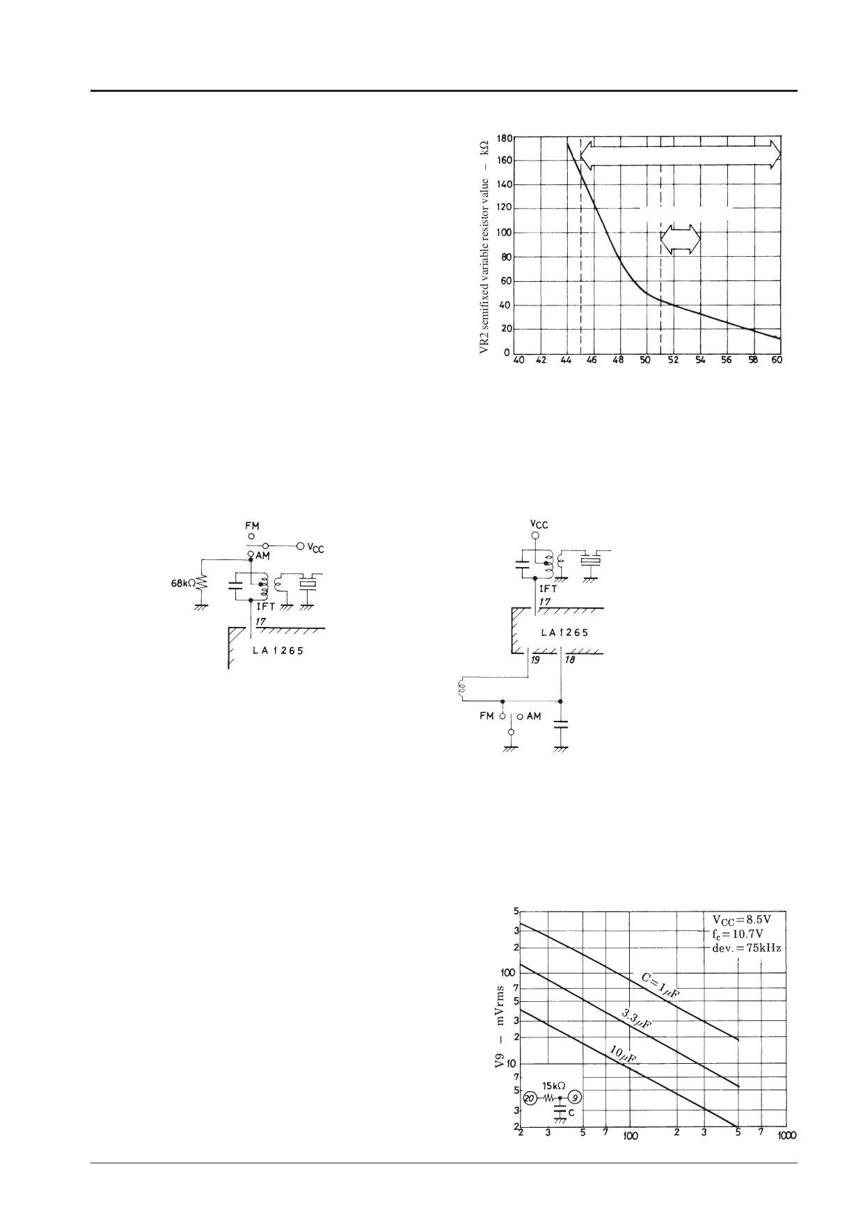
• LED lighting sensitivity setting for FM.
– For the LED lighting sensitivity setting for FM, the IC
Semifixed Variable Resistor for FM
input may be 45dBµ to 60dBµ. With the variations in the
LED lighting sensitivity setting for FM
front end considered, it is ideal that the IC input in a
standard receiving set be 51dBµ to 54dBµ. The lower
value of VR2 for the LED lighting sensitivity setting is as
Ideal setting range
illustrated right. Since the variations in the front end cause
the IC input setting sensitivity to vary, it is recommended
to use a value of VR2 at an input voltage lower than a
standard setting by 6dB or greater. For example, if IC
input 53dBµ is taken as a standard, use VR2≤100kΩ at IC
input 47dBµ.
2. AM/FM changeover
• Two selections are available for changeover as shown below
IC input – dBµ
: (A) pin 17-used method and (B) pin 18-used method.
• For (A), the voltage on pin 17 relative to VCC (pin 7) must be within the range of –0.8V to +0.1V. If not within this
range, distortion and selectivity will get worse.
• For (A), a resistance of 68kΩ at the IFT cold terminal, which is used to prevent the changeover circuit from
malfunctioning, must be connected.
(A) pin 17-use method for AM/FM changeover (B) Pin 18-used method for AM/FM changeover
3. Local OSC buffer output
• When local OSC buffer output wave form is saw-toothed at the SW mode, connect a resistance of 1.2kΩ or
thereabouts across pin 22 and GND.
4. AM input pin
• It is desirable that the AM input pin (pin 19) be L-coupled to pin 18.
• Inputting to pin 19 can be done by DC-cutting with a capacitor. However, an unbalance in the RF amplifier
(differential amplifier) causes gain drop and whistle worsening.
5. Capacitance across pin 9 and GND.
V9 – Modulation Frequency
A large capacitance across pin 9 and GND may cause a misstop
at an adjacent channel when the channel select speed is made
faster at the automatic channel select mode. In this case, decrease
the capacitance across pin 9 and GND. However, if too
decreased, the LED will flutter at low modulation frequencies at
the time of detuning. Therefore, it is recommended to fix the
capacitance across pin 9 and GND to be 3.3µF to 10µF. The
relation between modulation frequency and demodulation output
voltage on pin 9 with the capacitance across pin 9 and GND as a
parameter is shown right.
Modulation frequency – Hz
No.1820-4/15
Share Link: 