STR-F6600 Просмотр технического описания (PDF) - Allegro MicroSystems
Номер в каталоге
Компоненты Описание
производитель
STR-F6600 Datasheet PDF : 16 Pages
| |||
Series STR-F6600
OFF-LINE
QUASI-RESONANT FLYBACK
SWITCHING REGULATORS
Functional Description and Operation (cont’d)
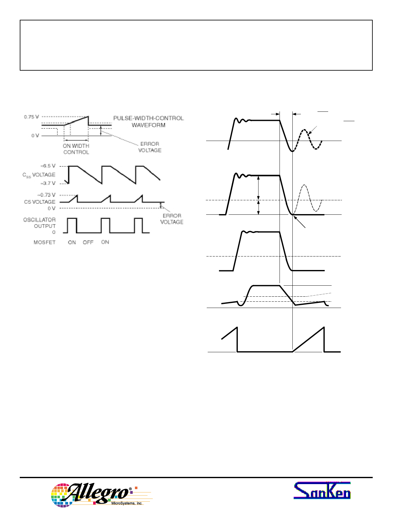
VP
t = π√LpC4
f R = 1/2π√LpC4
VDS
VD
Figure 7 - Voltage Regulation Waveforms
VP
VIN
VDS (min)
Normal Operation (Quasi-Resonant) Mode
Refer to the Functional Block Diagram, Typical Appli-
cation diagram (figure 6), and Quasi-Resonance Wave-
forms (figure 8).
Regulation is achieved as in fixed off-time mode but
instead of having a fixed off-time, the demagnetization of
the transformer is sensed by a second comparator. This
comparator threshold, Vth(2) is nominally 1.45 V. Quasi-
resonance sensing makes use of the natural magnetizing
and leakage inductances and self-capacitances of the
power circuit.
Figure 8 shows the drain voltage waveform, (VDS), on
pin 3 of the STR-F66xx, as well as VP, the voltage on the
primary of the transformer.
Once the current in the output diode stops flowing, the
primary stored energy ‘rings’ as shown by VP and VDS.
The resonant frequency (fr) is determined by the magne-
tizing inductance of the transformer and the capacitor C4.
VFDBK
VOCP ≈ 2.8 V
Vth(2) ≈ 1.45 V
Vth(1) ≈ 0.73 V
ID
Dwg. GK-021
Figure 8 – Quasi-Resonance Waveforms
The addition of this capacitor sets the ringing frequency
and reduces the harmonic content in the VDS waveform,
lowering EMI. Also since VDS falls to a minimum during
the first half-cycle of the ring this point can be sensed and
used to turn on the MOSFET with minimum voltage
across it. Thus the MOSFET is low voltage and zero
current switched (LVS/ZCS).
™TM
8
115 Northeast Cutoff, Box 15036
Worcester, Massachusetts 01615-0036 (508) 853-5000
Share Link: 