A514RW Просмотр технического описания (PDF) - MicroPower Direct, LLC
Номер в каталоге
Компоненты Описание
производитель
A514RW Datasheet PDF : 2 Pages
| |||
Model Selection Guide
Input
Output
Model
Voltage (VDC)
Number
Nominal Range
Current (mA)
Full-Load No-Load
Reflected
Ripple
Current
(mA, Typ)
Voltage
(VDC)
Current
(mA, Max)
Current
(mA, Min)
Efficiency
(%, Typ)
A501RW
12
9.0 - 18.0
429
20
25
3.3 1,200.0
60.0
77
A502RW
12
9.0 - 18.0
514
20
25
5.0 1,000.0
50.0
81
A503RW
12
9.0 - 18.0
595
20
25
12.0 500.0
25.0
84
A504RW
12
9.0 - 18.0
595
20
25
15.0 400.0
20.0
84
A505RW
12
9.0 - 18.0
514
20
25
±5.0 ±500.0
±25.0
81
A506RW
12
9.0 - 18.0
595
20
25 ±12.0 ±250.0
±12.5
84
A507RW
12
9.0 - 18.0
595
20
25 ±15.0 ±200.0
±10.0
84
A511RW
24 18.0 - 36.0 209
5
15
3.3 1,200.0
60.0
79
A512RW
24 18.0 - 36.0 251
5
15
5.0 1,000.0
50.0
83
A513RW
24 18.0 - 36.0 291
5
15
12.0 500.0
25.0
86
A514RW
24 18.0 - 36.0 291
5
15
15.0 400.0
20.0
86
A515RW
24 18.0 - 36.0 251
5
15
±5.0 ±500.0
±25.0
83
A516RW
24 18.0 - 36.0 291
5
15 ±12.0 ±250.0
±12.5
86
A517RW
24 18.0 - 36.0 291
5
15 ±15.0 ±200.0
±10.0
86
A521RW
48 36.0 - 75.0 104
3
10
3.3 1,200.0
60.0
79
A522RW
48 36.0 - 75.0 126
3
10
5.0 1,000.0
50.0
83
A523RW
48 36.0 - 75.0 145
3
10
12.0 500.0
25.0
86
A524RW
48 36.0 - 75.0 145
3
10
15.0 400.0
20.0
86
A525RW
48 36.0 - 75.0 126
3
10
±5.0 ±500.0
±25.0
83
A526RW
48 36.0 - 75.0 145
3
10 ±12.0 ±250.0
±12.5
86
A527RW
48 36.0 - 75.0 145
3
10 ±15.0 ±200.0
±10.0
86
A551RW
5
4.5 - 7.0 1,056
70
100
3.3 1,200.0
60.0
75
A552RW
5
4.5 - 7.0 1,265
70
100
5.0 1,000.0
50.0
79
A553RW
5
4.5 - 7.0 1,463
70
100 12.0 500.0
25.0
82
A554RW
5
4.5 - 7.0 1,463
70
100 15.0 400.0
20.0
82
A555RW
5
4.5 - 7.0 1,265
70
100 ±5.0 ±500.0
±25.0
79
A556RW
5
4.5 - 7.0 1,463
70
100 ±12.0 ±250.0
±12.5
82
A557RW
5
4.5 - 7.0 1,463
70
100 ±15.0 ±200.0
±10.0
82
Notes:
1. When measuring output ripple, it is recommended that an external 0.47 μF ce-
ramic capacitor be placed from the +Vout pin to the -Vout pin for single output
units and from each output to common for dual output units. For noise sensitive
applications, the use of 3.3 μF capacitors will reduce the output ripple.
2. Transient recovery is measured to within a 1% error band for a load step change
of 75% to 100%.
3. Operation at no-load will not damage these units. However, they may not meet
all specifications.
4. Dual output units may be connected to provide a 10 VDC, 24 VDC or 30 VDC
output. To do this, connect the load across the positive (+Vout) and negative
(-Vout) outputs and float the output common.
5. The converter should be connected to a low ac-impedance source. An input source
with a highly inductive impedance may affect the stability of the converter. In
applications where the converter output loading is high and input power is sup-
plied over long lines, it may be necessary to use a capacitor on the input to insure
start-up.
In this case, it is recommended that a low ESR (ESR <1.0Ω at 100 kHz) capacitor
be mounted close to the converter. For 5V input units a 10 μF is recommended,
for 12V input units, a 3.3 μF; and for 24V & 48V units a 2.2 μF.
6. It is recommended that a fuse be used on the input of a power supply for protec-
tion. See the table above for the correct rating.
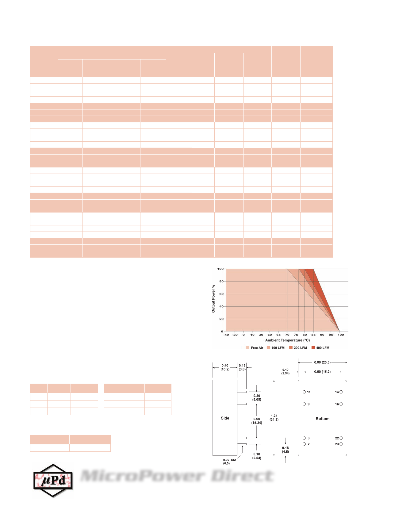
Derating Curve
Mechanical Dimensions
Fuse Rating
Slow-Blow
(mA)
1,500
1,500
1,500
1,500
1,500
1,500
1,500
700
700
700
700
700
700
700
350
350
350
350
350
350
350
3,000
3,000
3,000
3,000
3,000
3,000
3,000
Pin Connections
Pin Single Dual
Pin Single Dual
2, 3 -Vin
-Vin
9 No Pin Common
11
NC
-Vout
14
16
22, 23
+Vout
-Vout
+Vin
+Vout
Common
+Vin
NC: No Connection
Capacitive Load
Single Output Dual Output
6,800 μF Max ±1,000 μF Max
Mechanical Notes:
• All dimensions are typical in inches (mm)
• Tolerance x.xx = ±0.01 (±0.25)
• Leads are gold plated for improved
solderability.
MicroPower Direct
www.micropowerdirect.com
292 Page Street Ste D Stoughton, MA 02072 • TEL: (781) 344-8226 • FAX: (781) 344-8481 • E-Mail: sales@micropowerdirect.com
Share Link: 