AN6783S Просмотр технического описания (PDF) - Panasonic Corporation
Номер в каталоге
Компоненты Описание
производитель
AN6783S Datasheet PDF : 9 Pages
| |||
ICs for Timer
AN6783S
s Usage Notes
Pay attention to the following matters in order to prevent the destruction during the use and to increase the reliability ;
1. In the application circuit example, the calculated value by the theoretical equation for timer interval calculation and
the characteristics curve vary depending on the precision of the time interval capacitor used in the actual set. Take
such matter of the above into consideration.
Also, the proportional constant α depends on the kinds and characteristics of the time interval resistor and time
interval capacitor.
Make a final confirmation with the finished products.
In the case when a high precision is required, adjust the value by using a variable resistor as the time interval
resistor.
2. Use a time interval resistor in the range of 1 kΩ to 1 MΩ, and a time interval capacitor in the range of 0.1 µF to
100 µF which is polyester or tantalum electrolytic capacitor with a small tanδ value.
3. Connect a capacitor (1 µF to 10 µF) to the VS terminal in order to protect the IC from an external noise and stabilize
its operation.
4. If turning on power again after an extremely short-time power supply off state during the normal operation, be
careful that there may be a case that the automatic reset (power-on reset) fails due to a residual potential of the
external capacitance.
5. Take measures against noise in order to avoid the malfunction caused by the external noise. Pay attention to the
noise from an external source especially at setting a long interval time.
6. When connecting a plunger or relay to the output circuit, connect a diode to the both ends of coil in order to
protect the IC from the counter-electromotive force generted after the circuit is turned off .
7. Do not short circuit the VS terminal with VCC terminal in order to avoid malfunction.
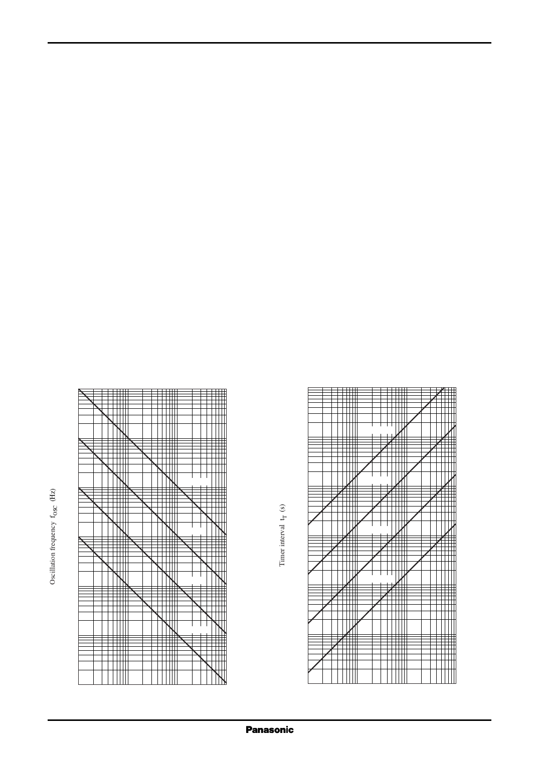
s Main Characteristics
fOSC Rt
104
106
tT Rt
Ct = 100 µF
103
105
102
Ct = 0.1 µF
104
Ct = 10 µF
10
Ct = 1 µF
103
Ct = 1 µF
1
Ct = 10 µF
102
Ct = 0.1 µF
10−1
Ct = 100 µF
10
10−2
1
10
102
103
Time decision resistance Rt (kΩ)
1
1
10
102
103
Time decision resistance Rt (kΩ)
5
Share Link: 