BA4911 Просмотр технического описания (PDF) - ROHM Semiconductor
Номер в каталоге
Компоненты Описание
производитель
BA4911 Datasheet PDF : 3 Pages
| |||
Electrical characteristics (Unless otherwise noted; Ta=25˚C, Vcc=14.4V)
Parameter
Symbol Min.
Standby circuit current 1
Standby circuit current 2
IST1
-
IST2
-
Output voltage (VDD) 1
VO1
4.80
Min. I/O voltage difference 1
Min. I/O voltage difference 2
∆VO1
-
∆VO1'
-
Output current capacity
Output voltage (AUDIO) 2
Min. I/O voltage difference
Output current capacity
I/O voltage difference (P.COM) 3
Output current capacity
IO1
VO2
∆VO2
IO2
∆VO3
IO3
300
7.80
-
200
-
300
I/O voltage difference (P.ANT) 4
∆VO4
-
Output current capacity
IO4
300
Output voltage (AM) 5
Min. I/O voltage difference
Output current capacity
VO5
7.5
∆VO5
-
IO5
50
Output voltage (FM) 6
Min. I/O voltage difference
Output current capacity
VO6
7.8
∆VO6
-
IO6
50
Output voltage (ILM) 7
VO7
9.9
Min. I/O voltage difference
∆VO7
-
Output current capacity
IO7
250
*1 Design guaranteed
∗This product is not designed for protection against radioactive rays.
∗Output current capacity must be set below MINIMUM.
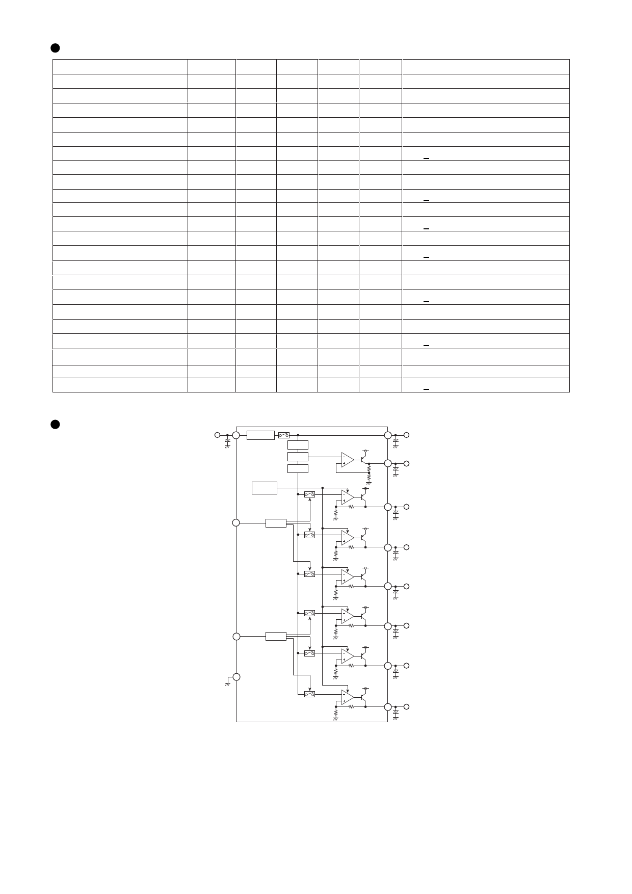
Block Diagram
Vcc
7
Over voltage
protection
Typ.
100
100
5.00
0.4
2.5
-
8.12
0.4
-
0.4
-
0.4
-
7.9
0.4
-
8.12
0.4
-
10.3
0.4
-
Pre Reg.
Vref
Vbuf
Max.
150
150
5.20
0.7
3.0
-
8.30
0.7
-
0.7
-
0.7
-
8.3
0.7
-
8.3
0.7
-
10.7
0.7
-
Unit
Conditions
µA Vcc=13.2V
µA
V
IO=300mA, Vcc=10~18V
V
IO=300mA, VBU-VO1
V
IO=300mA, Vcc-VO1
mA VO1≥4.8V
V
IO2=200mA, Vcc=10~18V, -30°C~80°C *1
V
IO2=200mA, Vcc-VO2
mA VO2≥7.8V
V
IO3=200mA
mA VO3≥13.7V
V
IO4=200mA
mA VO4≥13.7V
V
IO5=50mA, Vcc=10~18V, -30°C~80°C *1
V
IO5=50mA
mA VO5≥7.5V
V
IO6=50mA, Vcc=10~18V, -30°C~80°C *1
V
IO6=50mA, Vcc-VO6
mA VO6≥7.8V
V
IO7=250mA, Vcc=10~18V
V
IO7=250mA, Vcc-VO7
mA VO7≥9.9V
VBU
9
Vcc
8 VDD
Thermal
shut down
SW1 10
4 State
Vcc
AUDIO
6
Vcc
P.CON
2
Vcc
P.ANT
3
Vcc
SW2 11
3 State
AM
5
Vcc
GND 1
FM
4
Vcc
BA4911
ILM
12
Share Link: 