BTA10G-6-B-TF3-T Просмотр технического описания (PDF) - Unisonic Technologies
Номер в каталоге
Компоненты Описание
производитель
BTA10G-6-B-TF3-T Datasheet PDF : 3 Pages
| |||
BTA10
Preliminary
TRIACS
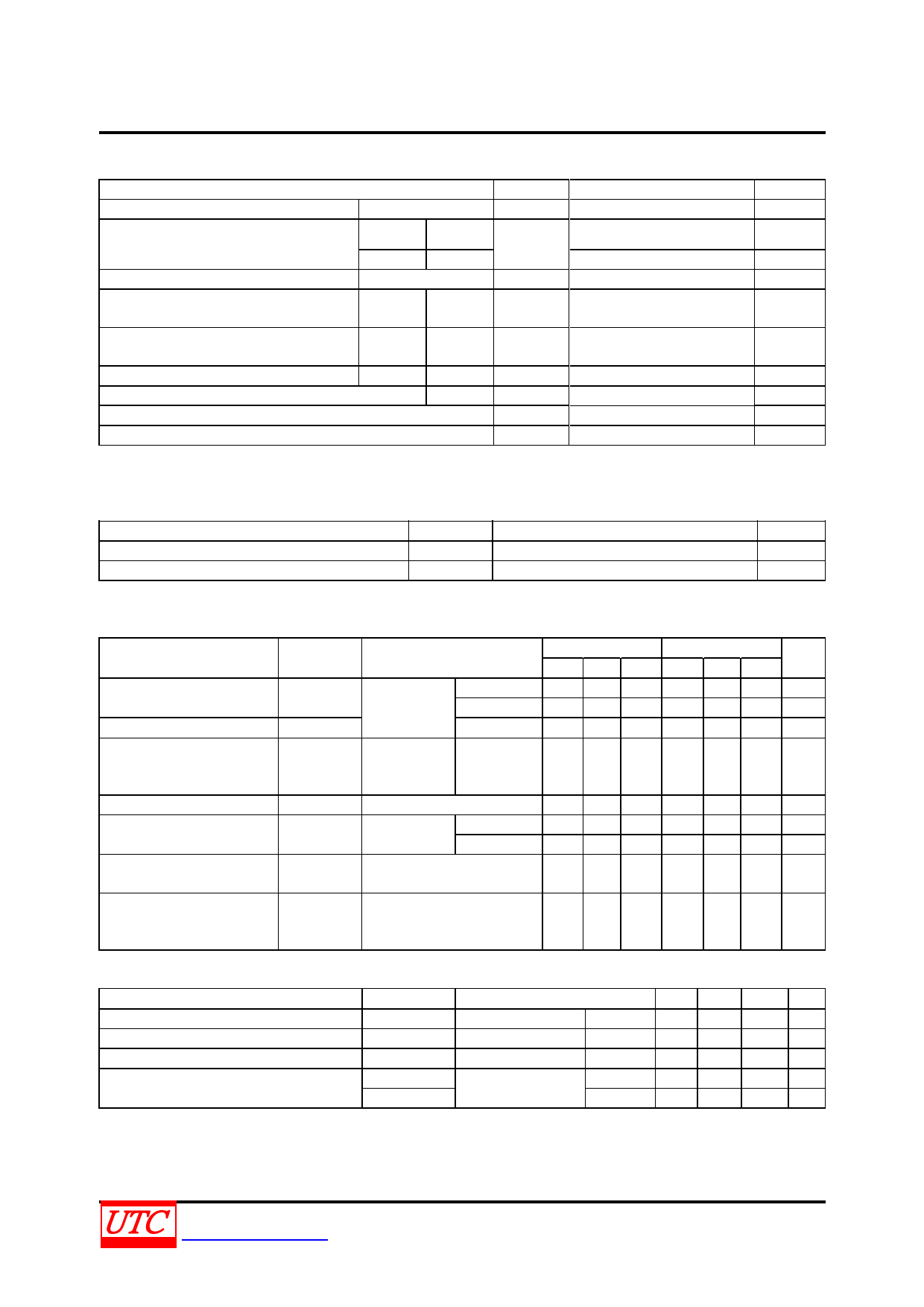
ABSOLUTE MAXIMUM RATINGS
PARAMETER
RMS On-State Current (Full Sine Wave) TC=95°C
SYMBOL
IT(RMS)
RATINGS
10
UNIT
A
Non Repetitive Surge Peak On-State
Current (Full Cycle TJ initial=25°C)
F=50Hz t=20ms
F=60Hz t=16.7ms
ITSM
100
105
A
A
I2t Value for Fusing
tP=10ms
I2t
55
A2s
Critical Rate of Rise of On-State Current:
IG=2xIGT, tr≤100ns
F=120Hz
TJ=125°C
dI/dt
Non Repetitive Surge Peak Off-State
Voltage
tP=10ms TJ=25°C VDSM/VRSM
50
VDSM/VRSM+100
A/µs
V
Peak Gate Current
tP=20µs TJ=125°C
IGM
4
A
Average Gate Power Dissipation
TJ=125°C PG(AV)
1
W
Operating Junction Temperature
Storage Junction Temperature
TJ
-40~+125
°C
TSTG
-40~+150
°C
Note: Absolute maximum ratings are those values beyond which the device could be permanently damaged.
Absolute maximum ratings are stress ratings only and functional device operation is not implied.
THERMAL RESISTANCES
PARAMETER
Junction to Ambient
Junction to Case (AC)
SYMBOL
θJA
θJC
RATINGS
60
2.4
ELECTRICAL CHARACTERISTICS (TJ= 25°C, unless otherwise specified)
UNIT
°C/W
°C/W
FOR STANDARD (4 QUADRANTS)
PARAMETER
SYMBOL
TEST CONDITIONS
C
MIN TYP
MAX
MIN
B
TYP
MAX
UNIT
Gate Trigger Current
(Note 1)
Gate Trigger Voltage
IGT
VD=12V,
VGT
RL=33Ω
I-II-III
IV
ALL
25
50 mA
50
100 mA
1.3
1.3 V
Gate Non-Trigger Voltage
Holding Current (Note 2)
VD=VDRM,
VGD
RL=3.3kΩ, ALL
TJ=125°C
IH
IT=500mA
0.2
0.2
V
25
50 mA
Latching Current
IL
IG=1.2IGT
I-III-IV
II
40
50 mA
80
100 mA
Critical Rate of Rise of
Off-State Voltage (Note 2)
dV/dt
VD=67%VDRM, Gate Open,
TJ=125°C
200
400
V/µs
Critical Rate of Rise of
Off-State Voltage at
Commutation (Note 2)
(dV/dt)c (dI/dt)c=4.4A/ms, TJ= 125°C 5
10
V/µs
STATIC CHARACTERISTICS
PARAMETER
SYMBOL
Peak On-State Voltage (Note 2)
VT
Threshold Voltage (Note 2)
VTO
Dynamic Resistance (Note 2)
RD
Repetitive Peak Off-State Current
IDRM
IRRM
Note: 1. Minimum IGT is guaranteed at 5% of IGT max.
2. For both polarities of MT2 referenced to MT1.
TEST CONDITIONS
MIN TYP MAX UNIT
ITM=14A, tP=380μs
VDRM=VRRM
TJ=25°C
TJ=125°C
TJ=125°C
TJ=25°C
TJ=125°C
1.55 V
0.85 V
40 mΩ
5 μA
1 mA
UNISONIC TECHNOLOGIES CO., LTD
www.unisonic.com.tw
2 of 3
QW-R401-031.d
Share Link: 