7314 Просмотр технического описания (PDF) - Princeton Technology
Номер в каталоге
Компоненты Описание
производитель
7314 Datasheet PDF : 20 Pages
| |||
4-Channel Input Audio Processor
7314
ACKNOWLEDGE
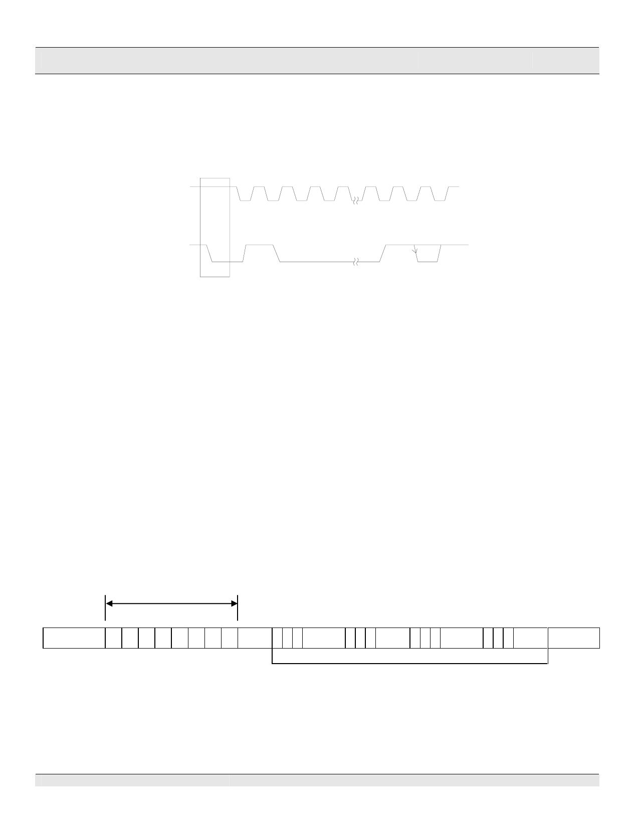
During the Acknowledge Clock Pulse, the master (µP) puts a resistive HIGH level on the DATA Line.
The peripheral (audio processor) that acknowledges has to pull-down (LOW) the DATA line during the
Acknowledge Clock Pulse so that the DATA Line is in a Stable Low State during this Clock Pulse.
Please refer to the diagram below.
CLK
1
2
3
4
7
8
9
DATA
MSB
START
AC KNOWLED GE MENT
FROM RECE IV ER
The audio processor that has been addressed has to generate an acknowledge after receiving each
byte, otherwise, the DATA Line will remain at the High Level during the ninth (9th) Clock Pulse. In this
case, the master transmitter can generate the STOP Information in order to abort the transfer.
TRANSMISSION WITHOUT ACKNOWLEDGE
If you want to avoid the acknowledge detection of the audio processor, a simpler µP transmission may
be used. Wait one clock and do not check the slave acknowledge of this same clock then send the new
data. If you use this approach, there are greater chances of faulty operation as well as decrease in
noise immunity.
INTERFACE PROTOCOL
The interface protocol consists of the following (see diagram below):
• A Start Condition
• A Chip Address Byte including the 7314 address. The 8th Bit of the Byte must be “0”. 7314 must
always acknowledge the end of each transmitted byte.
• A Data Sequence (N-Bytes + Acknowledge)
• A Stop Condition
7314 Address
MSB First Byte
LSB
MSB
LSB MSB
LSB
START 1 0 0 0 1 0 0 0 ACK
DATA
ACK
DATA
ACK
DATA TRANSMITTED (N-BYTES+ACKNOWLEDGE)
STOP
Note:
ACK = ACKNOWLEDGE
MAX. CLOCK SPEED = 100KBITS/S
7314 V1.0
-6-
January, 2007
Share Link: 