VS-12CTQ045SPBF Просмотр технического описания (PDF) - Vishay Semiconductors
Номер в каталоге
Компоненты Описание
производитель
VS-12CTQ045SPBF Datasheet PDF : 8 Pages
| |||
VS-12CTQ...SPbF, VS-12CTQ...-1PbF Series
Vishay High Power Products Schottky Rectifier,
2x6A
175
170
165
DC
160
Square wave (D = 0.50)
80 % rated VR applied
155
See note (1)
150
0
2
4
6
8
10
IF(AV) - Average Forward Current (A)
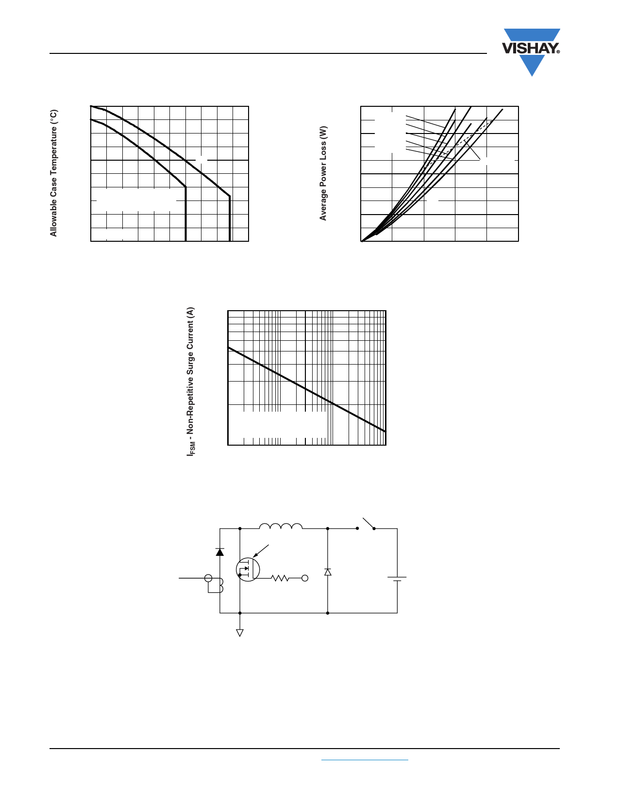
Fig. 5 - Maximum Allowable Case Temperature vs. Average
Forward Current (Per Leg)
1000
5.0
4.5
D = 0.20
D = 0.25
4.0
D = 0.33
D = 0.50
3.5
D = 0.75
3.0
2.5
RMS limit
2.0
1.5
DC
1.0
0.5
0
0
2
4
6
8
10
IF(AV) - Average Forward Current (A)
Fig. 6 - Forward Power Loss Characteristics (Per Leg)
At any rated load condition
and with rated VRRM applied
following surge
100
10
100
1000
10 000
tp - Square Wave Pulse Duration (µs)
Fig. 7 - Maximum Non-Repetitive Surge Current (Per Leg)
D.U.T.
Current
monitor
L
IRFP460
Rg = 25 Ω
High-speed
switch
Freewheel
diode
+ Vd = 25 V
40HFL40S02
Fig. 8 - Unclamped Inductive Test Circuit
Note
(1) Formula used: TC = TJ - (Pd + PdREV) x RthJC;
Pd = Forward power loss = IF(AV) x VFM at (IF(AV)/D) (see fig. 6);
PdREV = Inverse power loss = VR1 x IR (1 - D); IR at VR1 = 80 % rated VR
www.vishay.com
4
For technical questions, contact: diodestech@vishay.com
Document Number: 94131
Revision: 12-Mar-10
Share Link: 