IRU3037 Просмотр технического описания (PDF) - International Rectifier
Номер в каталоге
Компоненты Описание
производитель
IRU3037 Datasheet PDF : 21 Pages
| |||
IRU3037/IRU3037A & (PbF)
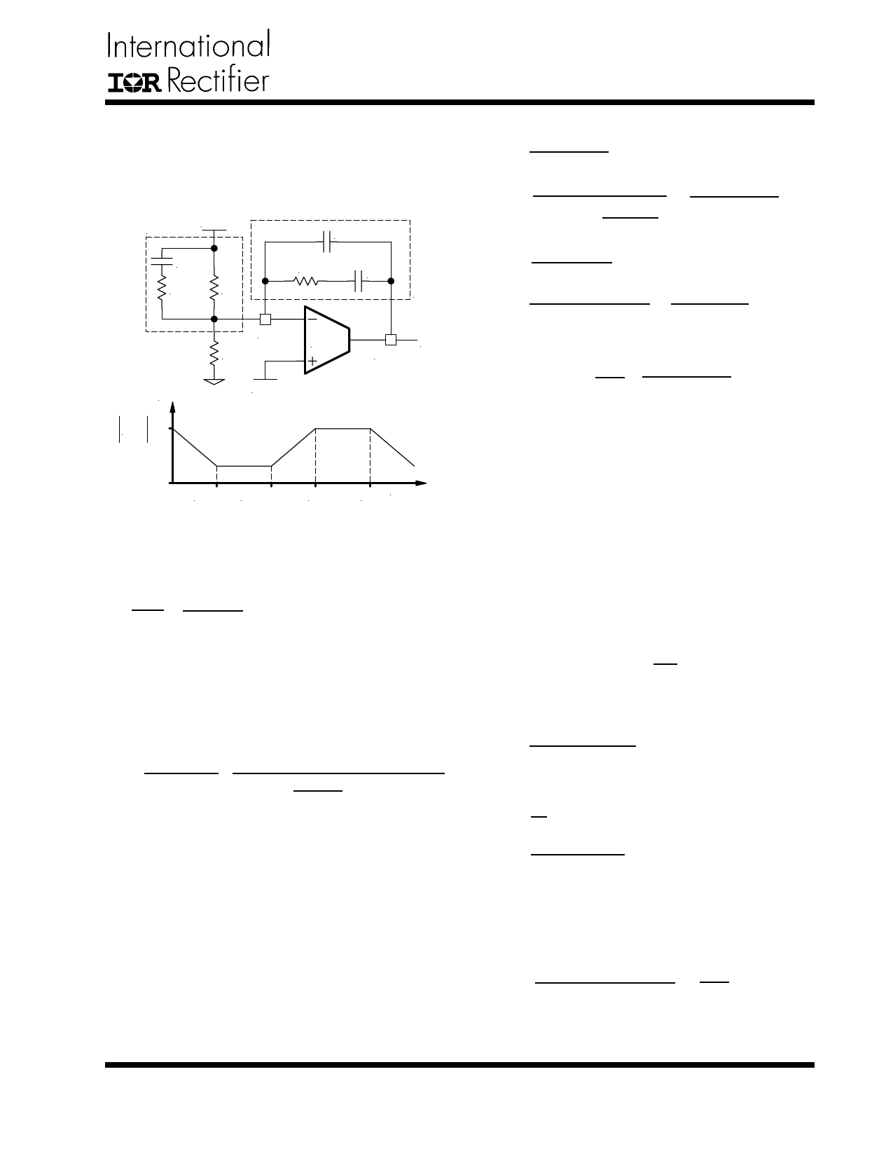
For a general solution for unconditionally stability for any
type of output capacitors, in a wide range of ESR values
we should implement local feedback with a compensa-
tion network. The typically used compensation network
for voltage-mode controller is shown in Figure 7.
ZIN
VOUT
C12
C10
R8
R6
R7
C11
Zf
Gain(dB)
H(s) dB
Fb
R5
VREF
E/A
Ve
Comp
FZ1
FZ2
FP2
FP3 Frequency
Figure 7 - Compensation network with local
feedback and its asymptotic gain plot.
In such configuration, the transfer function is given by:
Ve
VOUT
=
1 - gmZf
1 + gmZIN
The error amplifier gain is independent of the transcon-
ductance under the following condition:
gmZf >> 1 and gmZIN >>1
---(14)
By replacing ZIN and Zf according to Figure 7, the trans-
former function can be expressed as:
[ ( )] H(s)= sR6(C112+C11)×
(1+sR7C11)×[1+sC10(R6+R8)]
1+sR7
C12×C11
C12+C11
×(1+sR8C10)
As known, transconductance amplifier has high imped-
ance (current source) output, therefore, consider should
be taken when loading the E/A output. It may exceed its
source/sink output current capability, so that the ampli-
fier will not be able to swing its output voltage over the
necessary range.
The compensation network has three poles and two ze-
ros and they are expressed as follows:
FP1 = 0
FP2
=
1
2π×R8×C10
( ) FP3 =
1
2π×R7×
C12×C11
C12+C11
≅
1
2π×R7×C12
FZ1 =
1
2π×R7×C11
1
FZ2 = 2π×C10×(R6 + R8)
≅
1
2π×C10×R6
Cross Over Frequency:
FO = R7×C10× VVOISNC×
1
2π×Lo×Co
Where:
VIN = Maximum Input Voltage
VOSC = Oscillator Ramp Voltage
Lo = Output Inductor
Co = Total Output Capacitors
---(15)
The stability requirement will be satisfied by placing the
poles and zeros of the compensation network according
to following design rules. The consideration has been
taken to satisfy condition (14) regarding transconduc-
tance error amplifier.
1) Select the crossover frequency:
Fo < FESR and Fo ≤ (1/10 ~ 1/6)× fS
2
2) Select R7, so that R7 >> gm
3) Place first zero before LC’s resonant frequency pole.
FZ1 ≅ 75% FLC
C11 =
1
2π × FZ1 × R7
4) Place third pole at the half of the switching frequency.
FP3 =
fS
2
C12
=
2π
×
1
R7
×
FP3
C12 > 50pF
If not, change R7 selection.
5) Place R7 in (15) and calculate C10:
C10 ≤
2π × Lo × Fo × Co
R7
×
VOSC
VIN
www.irf.com
9
Share Link: 