AD592(RevA) Просмотр технического описания (PDF) - Analog Devices
Номер в каталоге
Компоненты Описание
производитель
AD592 Datasheet PDF : 8 Pages
| |||
AD592
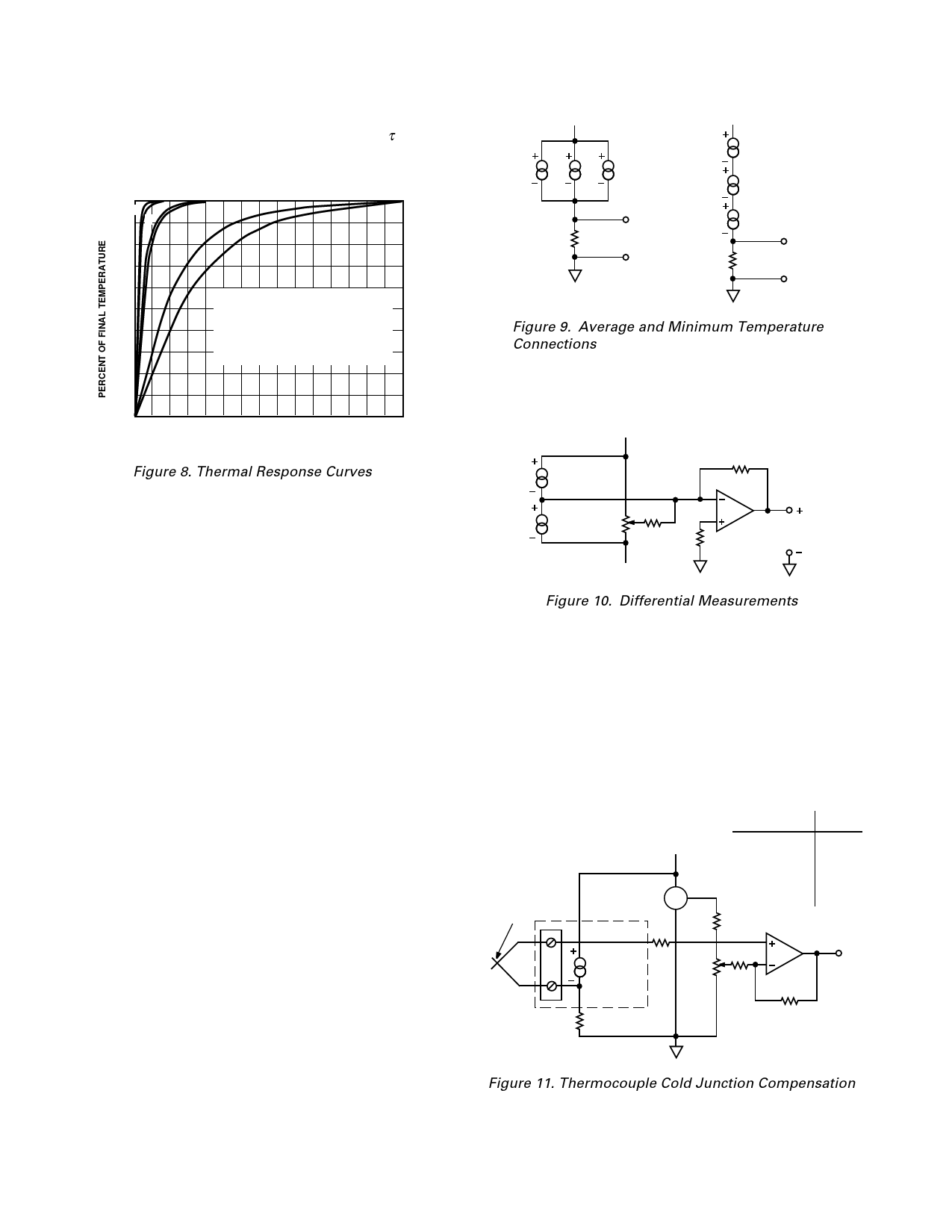
Response of the AD592 output to abrupt changes in ambient
temperature can be modeled by a single time constant τ expo-
nential function. Figure 8 shows typical response time plots for
several media of interest.
100
A
C
90 B
D
80
E
70
F
60
50
40
30
20
10
A ALUMINUM BLOCK
B FLUORINERT LIQUID
C MOVING AIR (WITH HEAT SINK)
D MOVING AIR (WITHOUT HEAT SINK)
E STILL AIR (WITH HEAT SINK)
F STILL AIR (WITHOUT HEAT SINK)
0 20 40 60 80 100 120 140 160 180 200 220 240 260 280 300
TIME – sec
Figure 8. Thermal Response Curves
The time constant, τ, is dependent on θJA and the thermal ca-
pacities of the chip and the package. Table I lists the effective τ
(time to reach 63.2% of the final value) for several different
media. Copper printed circuit board connections where ne-
glected in the analysis, however, they will sink or conduct heat
directly through the AD592’s solder dipped Kovar leads. When
faster response is required a thermally conductive grease or glue
between the AD592 and the surface temperature being mea-
sured should be used. In free air applications a clip-on heat sink
will decrease output stabilization time by 10-20%.
MOUNTING CONSIDERATIONS
If the AD592 is thermally attached and properly protected, it
can be used in any temperature measuring situation where the
maximum range of temperatures encountered is between –25°C
and +105°C. Because plastic IC packaging technology is em-
ployed, excessive mechanical stress must be safeguarded against
when fastening the device with a clamp or screw-on heat tab.
Thermally conductive epoxy or glue is recommended under
typical mounting conditions. In wet or corrosive environments,
any electrically isolated metal or ceramic well can be used to
shield the AD592. Condensation at cold temperatures can cause
leakage current related errors and should be avoided by sealing
the device in nonconductive epoxy paint or dips.
APPLICATIONS
Connecting several AD592 devices in parallel adds the currents
through them and produces a reading proportional to the aver-
age temperature. Series AD592s will indicate the lowest tem-
perature because the coldest device limits the series current
flowing through the sensors. Both of these circuits are depicted
in Figure 9.
+5V
AD592
333.3Ω
(0.1%)
VTAVG (1mV/K)
+15V
AD592
AD592
AD592
10kΩ
(0.1%)
VTAVG (10mV/K)
Figure 9. Average and Minimum Temperature
Connections
The circuit of Figure 10 demonstrates a method in which a
voltage output can be derived in a differential temperature
measurement.
+V
AD592
AD592
R1
50kΩ
5MΩ
10kΩ
10kΩ
AD741
VOUT = (T1 – T2) x
(10mV/oC)
–V
Figure 10. Differential Measurements
R1 can be used to trim out the inherent offset between the two
devices. By increasing the gain resistor (10 kΩ) temperature
measurements can be made with higher resolution. If the magni-
tude of V+ and V– is not the same, the difference in power con-
sumption between the two devices can cause a differential
self-heating error.
Cold junction compensation (CJC) used in thermocouple signal
conditioning can be implemented using an AD592 in the circuit
configuration of Figure 11. Expensive simulated ice baths or
hard to trim, inaccurate bridge circuits are no longer required.
MEASURING
JUNCTION
+7.5V
2.5V
AD1403
10kΩ
Cu
1kΩ
AD592
REFERENCE
Cu JUNCTION
100kΩ
THERMOCOUPLE
TYPE
J
K
T
E
S
R
APPROX.
R VALUE
52Ω
41Ω
41Ω
61Ω
6Ω
6Ω
AD OP07E
VOUT
RG2
(1kΩ)
RG1
R
Figure 11. Thermocouple Cold Junction Compensation
–6–
REV. A
Share Link: 