ADM705 Просмотр технического описания (PDF) - Analog Devices
Номер в каталоге
Компоненты Описание
производитель
ADM705 Datasheet PDF : 12 Pages
| |||
ADM705/ADM706/ADM707/ADM708
APPLICATIONS INFORMATION
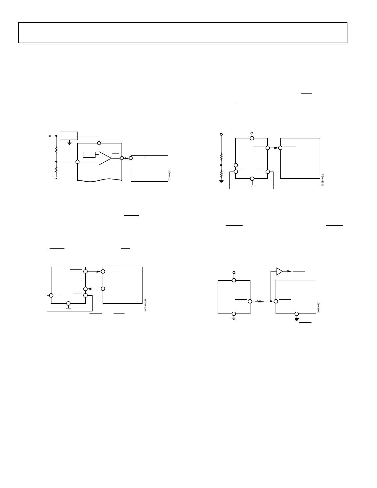
A typical application circuit is shown in Figure 18. The
unregulated dc input supply is monitored using PFI via the
resistive divider network. Resistor R1 and Resistor R2 should
be selected so that when the supply voltage drops below the
desired level (such as 8 V), the voltage on PFI drops below
the 1.25 V threshold, thereby generating an interrupt to the
microprocessor. Monitoring the preregulator input provides
additional time to execute an orderly shutdown procedure
before power is lost.
7V TO 15V
INPUT POWER
5V
ADP3367
R1
VCC
1.25V –
PFO
RESET
+
PFI
R2
ADM705/ADM706/
MICROPROCESSOR
ADM707/ADM708
Figure 18. Typical Application Circuit
Microprocessor activity is monitored using WDI. This is driven
using an output line from the processor. The software routines
should toggle this line at least once every 1.60 seconds. If a
problem occurs and this line is not toggled, WDO goes low and
a nonmaskable interrupt is generated. This interrupt routine can be
used to clear the problem.
If, in the event of inactivity on the WDI line, a system reset
is required, WDO should be connected to MR, as shown in
Figure 19.
RESET
ADM705/
ADM706
WDI
MR
WDO
GND
RESET
MICROPROCESSOR
I/O LINE
Figure 19. RESET From WDO
MONITORING ADDITIONAL SUPPLY LEVELS
It is possible to use the power-fail comparator to monitor a
second supply as shown in Figure 20. The two sensing resistors,
R1 and R2, are selected so that the voltage on PFI drops below
1.25 V at the minimum acceptable input supply. PFO can be
connected to MR so that a reset is generated when the supply
drops out of tolerance. In this case, if either supply drops out
of tolerance, a reset is generated.
VX
5V
VCC
RESET
RESET
ADM705/
R1
ADM706
MICROPROCESSOR
PFI
R2
MR
PFO
GND
Figure 20. Monitoring 5 V and an Additional Supply, VX
MICROPROCESSOR WITH BIDIRECTIONAL RESET
To prevent contention for microprocessors with a bidirectional
reset line, a current limiting resistor should be inserted between
the ADM70x RESET output pin and the microprocessor RESET
pin. This limits the current to a safe level if there are conflicting
output reset levels. A suitable resistor value is 4.7 kΩ. If the reset
output is required for other uses, it should be buffered, as shown in
Figure 21.
5V
BUFFERED
RESET
VCC
ADM70x
RESET
GND
MICROPROCESSOR
RESET
GND
Figure 21. Bidirectional Input/Output RESET
Rev. G | Page 10 of 12
Share Link: 