ML4662 Просмотр технического описания (PDF) - Micro Linear Corporation
Номер в каталоге
Компоненты Описание
производитель
ML4662 Datasheet PDF : 12 Pages
| |||
ML4662
VCC
51Ω
51Ω
51Ω
RTSET = 560Ω
IOUT = 15.9mA
ECL
VCCTx
TxOUT
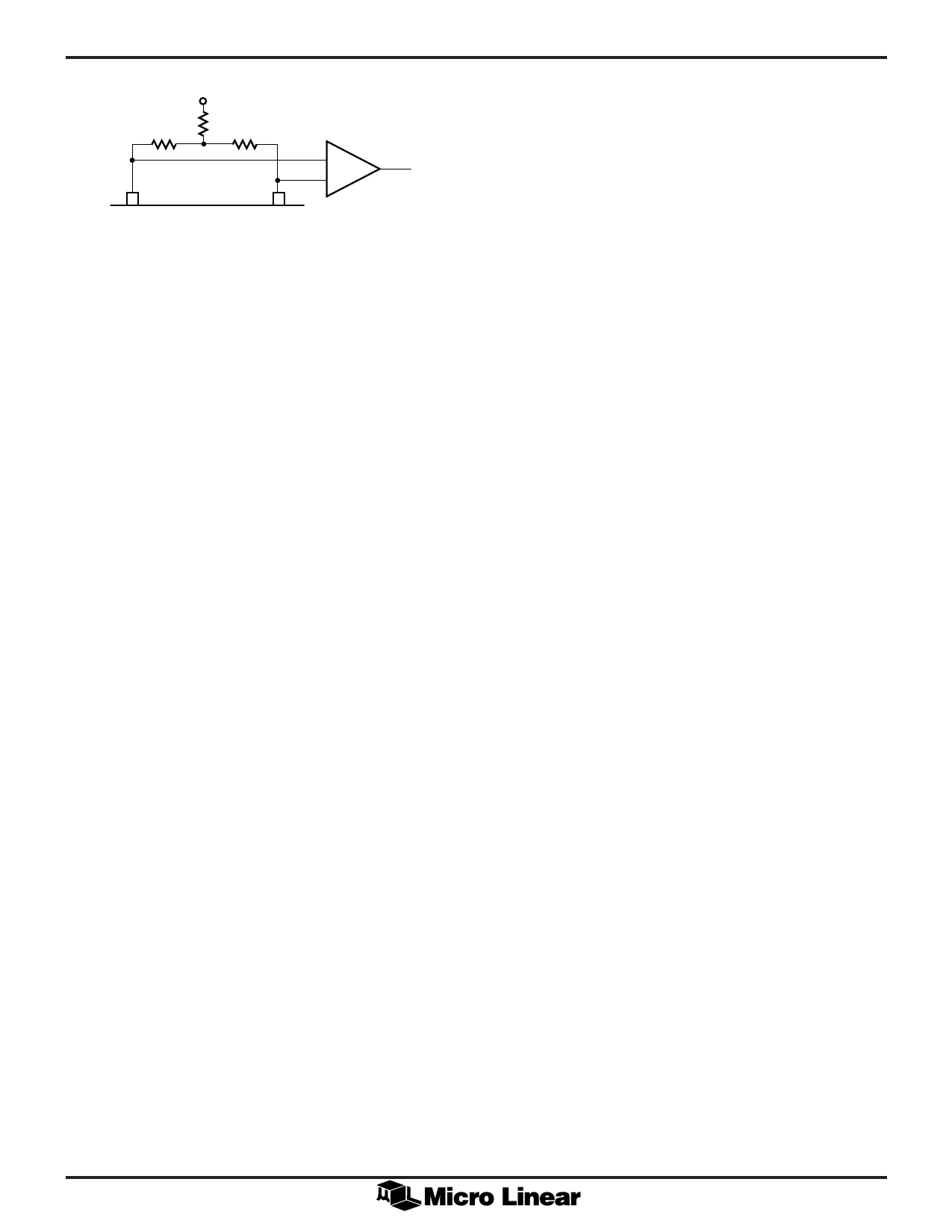
Figure 3. Converting Optical LED Driver Output to
Differential ECL.
If not driving an optical LED directly, a differential output
can be generated by tying resistors from VCCTx and TxOUT
to VCC as shown in Figure 3. The minimum voltage on
these two pins should not be less than VCC – 2V.
RECEPTION
The input to the transceiver comes from the ECL outputs
of the ML4622 or ML4624. At this point it is a clean
digital ECL signal. At the start of packet reception no more
than 2.5 bits are received from the fiber cable and not
transmitted onto the DI circuit. The receive squelch will
reject frequencies lower than 2.51MHz and will also
reject any receive input if the LMONIN pin is high.
While in the unsquelch state, the receive squelch circuit
looks for the start of idle signal at the end of the packet.
Start of idle occurs when the input signal remains idle for
more than 160ns. When start of idle is detected, the
receive squelch circuit returns to the squelch state and the
start of idle signal is output on the DI circuit (Rx+, Rx–).
COLLISION
Whenever the receiver and the transmitter are active at
the same time the chip will activate the collision output,
except when loopback is disabled (LBDIS = VCC). The
collision output is a differential square wave matching the
AUI specifications and capable of driving a 78Ω load. The
frequency of the square wave is 10MHz ± 15% with a 60/
40 to 40/60 duty cycle. The collision oscillator also is
activated during SQE Test and Jabber.
LOOPBACK
The loopback function emulates a 10Base-T transceiver
whereby the transmit data sent by the DTE is looped back
over the AUI receive pair. Some LAN controllers use this
loopback information to determine whether a MAU is
connected by monitoring the carrier sense while
transmitting. The software can use this loopback
information to determine whether a MAU is connected to
the DTE by checking the status of carrier sense after each
packet transmission.
When data is received by the chip while transmitting, a
collision condition exits. This will cause the collision
8
oscillator to turn on and the data on the DI pair will
follow RxIN±. After a collision is detected, the collision
oscillator will remain on until either DO or RxIN go idle.
Loopback can be disabled by strapping LBDIS to VCC. In
this mode the chip operates as a full duplex transmitter
and receiver, and collision detection is disabled. A
loopback through the transceiver can be accomplished by
tying the fiber transmitter to the receiver.
SQE TEST FUNCTION (SIGNAL QUALITY ERROR)
The SQE test function allows the DTE to determine
whether the collision detect circuitry is functional. After
each transmission, during the inter-packet gap time, the
collision oscillator will be activated for (typically) 1µs. The
SQE test will not be activated if the chip is in the low light
state, or the jabber on state.
For SQE to operate, the SQEN pin must be tied to VCC.
This allows the MAU to be interfaced to a DTE. The SQE
test can be disabled by tying the SQEN pin to ground, for
a repeater interface.
JABBER FUNCTION REQUIREMENTS
The Jabber function prevents a babbling transmitter from
bringing down the network. Within the transceiver is a
Jabber timer that starts at the beginning of each
transmission and resets at the end of each transmission. If
the transmission last longer than 20ms the jabber logic
disables the transmitter, and turns on the collision signal
COL+, COL–. When Tx+ and Tx– finally go idle, a second
timer measures 0.5 seconds of idle time before the
transmitter is enabled and collision is turned off. Even
though the transmitter is disabled during jabber, the 1MHz
idle signal is still transmitted.
LED DRIVERS
The ML4662 has five LED drivers. The LED driver pins are
active low, and the LEDs are normally off. The LEDs are
tied to their respective pins through a 500Ω resistor to 5
Volts.
The XMT, RCV and CLSN pins have pulse stretchers on
them which enables the LEDs to be visible. When
transmission or reception occurs, the LED XMT, RCV or
CLSN status pins will activate low for several
milliseconds. If another transmit, receive or collision
conditions occurs before the timer expires, the LED timer
will reset and restart the timing. Therefore rapid events
will leave the LEDs continuously on. The JAB and LMON
LEDs do not have pulse stretchers on them since their
conditions occur long enough for the eye to see.
LOW LIGHT CONDITION
The LMON LED output is used to indicate a low light
condition. LMON is activated low when both LMONIN is
low and there are transitions on RxIN± less than 3µs apart.
If either one of these conditions do not exist, LMON will
go high.
Share Link: 