UPD16431AGC-7ET Просмотр технического описания (PDF) - NEC => Renesas Technology
Номер в каталоге
Компоненты Описание
производитель
UPD16431AGC-7ET Datasheet PDF : 34 Pages
| |||
µPD16431A
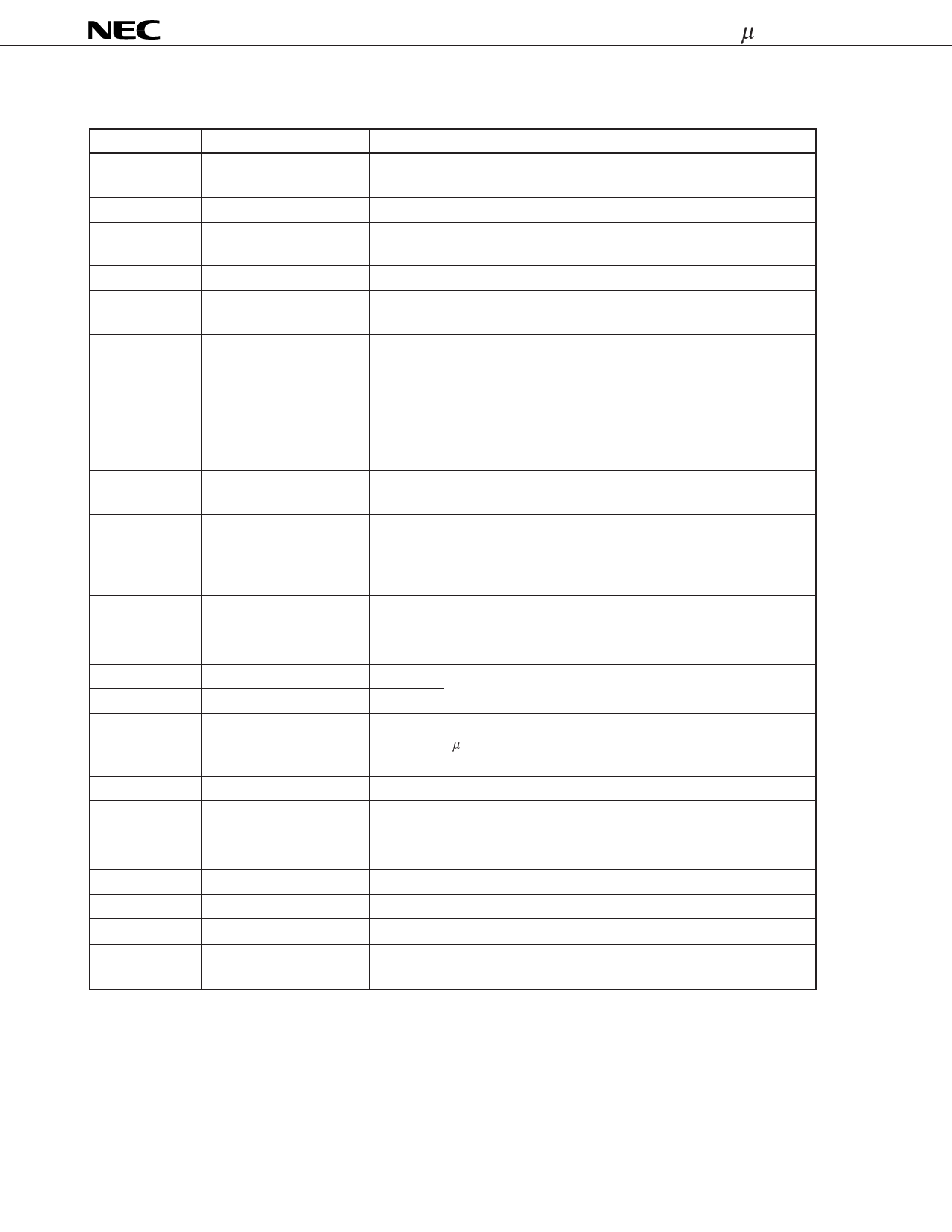
PIN FUNCTIONS
Symbol
SEG1/KS1 to
SEG8/KS8
SEG9 to SEG48
SEG49/LED1 to
SEG56/LED8
COM1 to COM4
SCK
Name
Segment output/key
source output
Segment output
Segment output/LED
output pins
Common output
Shift clock input
DATA
Data input/output
STB
LCD/LED
Strobe input
LCD/LED select
OE Note
Output enable input
OSCIN
OSCOUT
SYNC
Oscillation input
Oscillation output
Synchronizing signal
KEY1 to KEY4
KEY REQ
Key data input
Key request output
VDD
VSS
VLCD
VEE
VLC1 to VLC3
Logic power supply
Logic GND
LCD drive power supply
LCD GND
Power supply for LCD
drive
No.
25 to 32
33 to 72
73 to 80
21 to 24
7
8
9
10
11
Description
These pins serve as LCD segment output pins and key
source output pins for key scanning.
LCD segment output pins
These pins can be used as LCD segment output or LED
output pins depending on the setting of the LCD/LED pin.
LCD common output pins
Data shift clock. Data is read at the rising edge, and is
output at the falling edge of this clock.
This pin inputs a command or display data, or outputs
key data.
A command or data is input at the rising edge of the shift
clock, starting from the most significant bit. Key data is
output at the falling edge of the shift clock, starting from
the most significant bit.
This pin serves as an open-drain pin in the output mode.
Data can be input when this signal goes low. When it
goes high, command processing is performed.
When this signal goes high, the SEGn/LEDm pins function
as LCD segment output pins; when it goes low, they
function as LED driver output pins. The LED driver has a
drive capability of 15 mA and is N-ch open drain.
When this signal goes low, all the segment output and
LED output pins are off (SEGn = COMn = VLCD). Internal
data are saved.
12
13
14
2 to 5
6
15
1
16
20
17 to 19
Connect a resistor for oscillation circuit across these pins.
A synchronizing signal input pin. When two or more
µPD16431A’s are used, each device is wired-ORed. This
pin must be pulled up when this chip is used alone.
Key data input pins for key scanning
This signal goes high when a key is pressed (key data = H).
Read the key data only while this pin is high.
Power supply pin for internal logic
GND pin for internal logic and LED output
Power supply pin for LCD drive
GND pin for LCD drive
Power supply for driving dot matrix LCD
Note At OE = L, the key data cannot be written correctly, even when the display ON/OFF of the status
command is set to the “normal operation” (10). Also, in this state, unnecessary waveforms are
generated from between SEG1/KS1 to SEG8/KS8 during the key scanning period. (The display is OFF.)
4
Share Link: 