MAP3204 Просмотр технического описания (PDF) - Unspecified
Номер в каталоге
Компоненты Описание
производитель
MAP3204 Datasheet PDF : 11 Pages
| |||
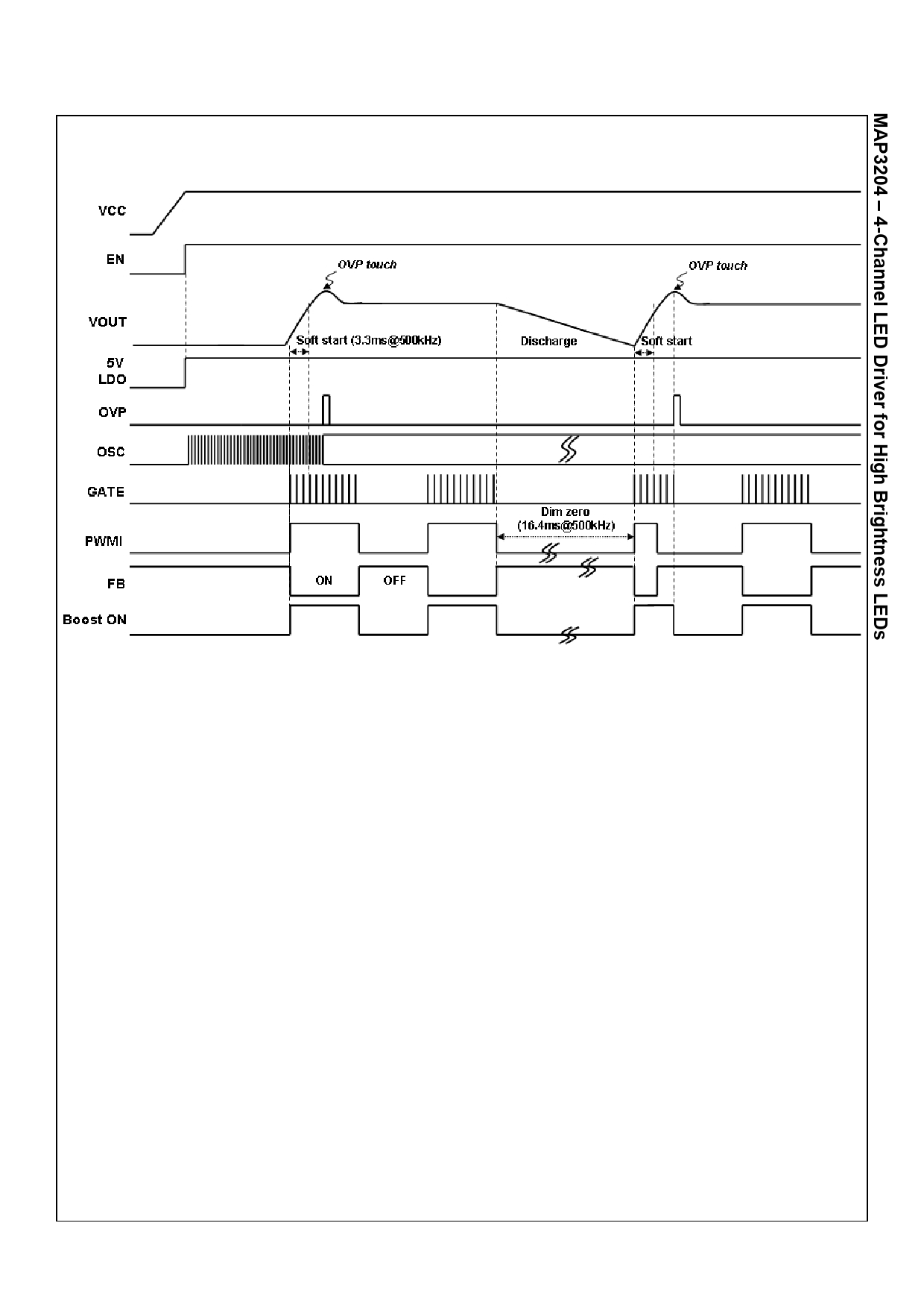
OPERATION TIMING CHART
Confidential
Preliminary Datasheet Version 0.0
After the enable turns on, the internal 5V LDO is powered up and the internal oscillator starts oscillation. If the PWMI
signal remains low at the initial state, the gate drive output to the external MOSFET also remains low, so the boost
controller dose not step up the output voltage. As soon as the PWMI signal turns on over than at least 1% duty cycle, the
controller performs soft-start and continues regulation throughout the PWMI on duty. In the meantime each FB’s are
turned on simultaneously and the constant current flows the LEDs. The timing between PWMI and FB is approximately
same.
If the PWMI signal remains low state over than 16.4ms at 500kHz boost switching frequency during normal operation,
the controller regards it as dim-zero condition. Because of discharge of output capacitor through the OVP sensing
resistors during the dim-zero time, the output voltage getting declined. So the controller performs soft-start to boost the
output voltage until it reaches the over-voltage-protection level with regarding the dimming duty cycle as 100%. For this
reason, some extra switching can be seen when the on duty of PWMI signal is less than the internal boost on period.
Jan. 28th 2011
Share Link: 