EVM-900-DT Просмотр технического описания (PDF) - Unspecified
Номер в каталоге
Компоненты Описание
производитель
EVM-900-DT Datasheet PDF : 38 Pages
| |||
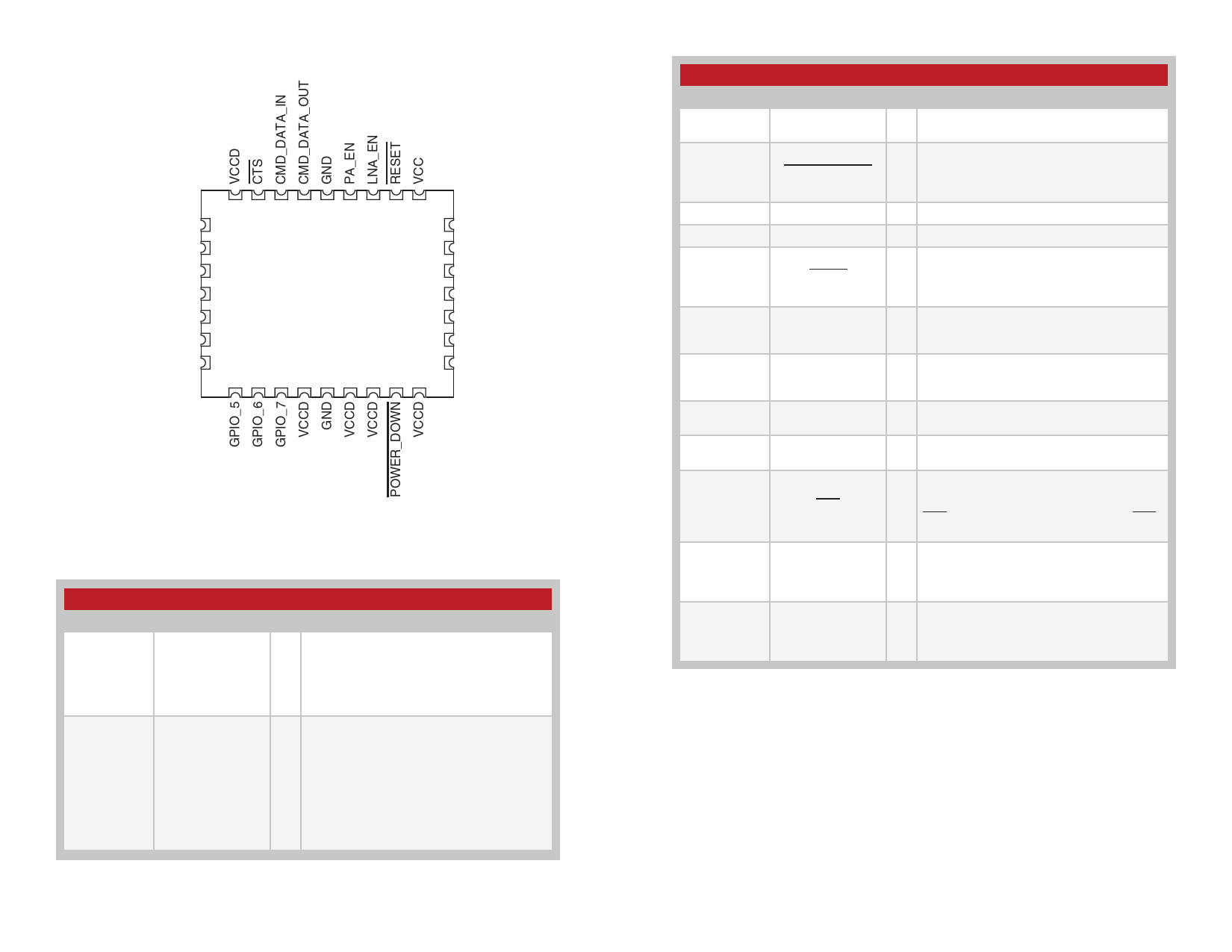
Pin Assignments
MODE_IND
ACTIVE
GPIO_0
GPIO_1
GPIO_2
GPIO_3
GPIO_4
29 28 27 26 25 24 23 22 21
30
20
31
19
32
18
1
17
2
16
3
15
4
14
5 6 7 8 9 10 11 12 13
GND
ANT
GND
GND
GND
GND
GND
Figure 13: HumDTTM Series Transceiver Pin Assignments (Top View)
Pin Descriptions
Pin Descriptions
Pin Number
Name
1, 2, 3, 4, 5,
6, 7, 32
GPIO_0–GPIO_7
8, 10, 11, 13,
29
VCCD
I/O Description
General Purpose I/O Lines. Each line can
be configured as either an analog input, a
I/O
digital input or a digital output. The digital
inputs can be configured to have either a
20kΩ pull up or pull down resistance or high
impedance (no resistors).
These lines are inputs that are pulled
to supply internally. They can be left
unconnected, but boards in noisy
environments or with noisy components in
—
the same product are recommended to pull
these lines to
random noise
VtoCCa. fTfehcet
potential exists for
the line and cause
unexpected operation. This risk is reduced
in simple, battery powered applications, but
should be considered in all designs.
– 10 –
Pin Descriptions
Pin Number
9, 14, 15, 16,
17, 18, 20, 25
Name
GND
12
POWER_DOWN
19
ANTENNA
21
VCC
22
RESET
23
LNA_EN
24
PA_EN
26
CMD_DATA_OUT
27
CMD_DATA_IN
28
CTS
30
MODE_IND
31
ACTIVE
I/O Description
— Ground
Power Down. Pulling this line low places the
I
module into a low-power state. The module
is not functional in this state. Pull high for
normal operation. Do not leave floating.
— 50-ohm RF Antenna Port
— Supply Voltage
This line resets the module when pulled low.
I
It should be pulled high for normal operation.
This line has an internal 10k resistor to
supply, so leave it unconnected if not used.
Low Noise Amplifier Enable. This line is
O driven high when receiving. It is intended to
activate an optional external LNA.
Power Amplifier Enable. This line is driven
O high when transmitting. It is intended to
activate an optional external power amplifier.
O
Command Data Out. Output line for the
serial interface commands
I
Command Data In. Input line for the serial
interface commands.
UART Clear To Send, active low. This line
indicates to the host microcontroller when
O the module is ready to accept data. When
CTS is high, the module is busy. When CTS
is low, the module is ready for data.
This output goes high when the module
O
is sending or receiving data over the air.
This line can directly drive an LED for visual
indication of activity.
This output goes high when the module is
O
powered on and functional. This line can
directly drive an LED for visual indication of
activity.
Figure 14: HumDTTM Series Transceiver Pin Descriptions
– 11 –
Share Link: 