BFC246958683 Просмотр технического описания (PDF) - Vishay Semiconductors
Номер в каталоге
Компоненты Описание
производитель
BFC246958683 Datasheet PDF : 15 Pages
| |||
End of Life September 2018 - Alternative Device: MKT467, MKT468
www.vishay.com
MKT469
Vishay BCcomponents
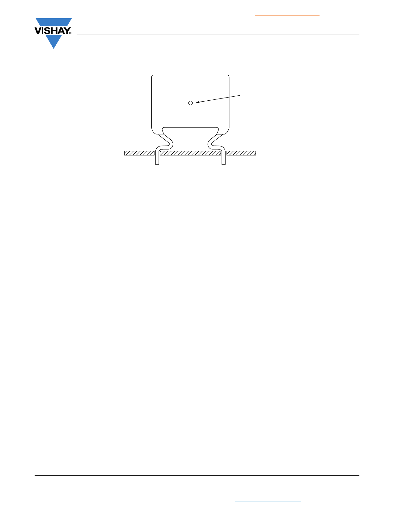
MEASURING THE COMPONENT TEMPERATURE
A thermocouple must be attached to the capacitor body as in:
Thermocouple
The temperature is measured in unloaded (Tamb) and maximum loaded condition (TC).
The temperature rise is given by T = TC - Tamb.
To avoid radiation or convection, the capacitor should be tested in a wind-free box.
APPLICATION NOTE AND LIMITING CONDITIONS
These capacitors are not suitable for mains applications as across-the-line capacitors without additional protection, as
described hereunder. These mains applications are strictly regulated in safety standards and therefore electromagnetic
interference suppression capacitors conforming the standards must be used.
For capacitors connected in parallel, normally the proof voltage and possibly the rated voltage must be reduced. For information
depending of the capacitance value and the number of parallel connections contact: dc-film@vishay.com
To select the capacitor for a certain application, the following conditions must be checked:
1. The peak voltage (UP) shall not be greater than the rated DC voltage (URDC)
2. The peak-to-peak voltage (UP-P) shall not be greater than 22 x URAC to avoid the ionization inception level
3. The voltage pulse slope (dU/dt) shall not exceed the rated voltage pulse slope in an RC-circuit at rated voltage and without
ringing. If the pulse voltage is lower than the rated DC voltage, the rated voltage pulse slope may be multiplied by URDC and
divided by the applied voltage.
For all other pulses following equation must be fulfilled:
T
2 x
d--d--U-t--
2
x
dt
URDC
x
d--d--U-t--
rated
0
T is the pulse duration.
The rated voltage pulse slope is valid for ambient temperatures up to 85 °C. For higher temperatures a derating factor of
3 % per K shall be applied.
4. The maximum component surface temperature rise must be lower than the limits (see graph “Max. allowed component
temperature rise”).
5. Since in circuits used at voltages over 280 V peak-to-peak the risk for an intrinsically active flammability after a capacitor
breakdown (short circuit) increases, it is recommended that the power to the component is limited to 100 times the values
mentioned in the table: “Heat Conductivity”
6. When using these capacitors as across-the-line capacitor in the input filter for mains applications or as series connected
with an impedance to the mains the applicant must guarantee that the following conditions are fulfilled in any case (spikes
and surge voltages from the mains included).
Revision: 27-Mar-18
10
Document Number: 28244
For technical questions, contact: dc-film@vishay.com
THIS DOCUMENT IS SUBJECT TO CHANGE WITHOUT NOTICE. THE PRODUCTS DESCRIBED HEREIN AND THIS DOCUMENT
ARE SUBJECT TO SPECIFIC DISCLAIMERS, SET FORTH AT www.vishay.com/doc?91000
Share Link: 