2SC54190RA Просмотр технического описания (PDF) - Panasonic Corporation
Номер в каталоге
Компоненты Описание
производитель
2SC54190RA Datasheet PDF : 3 Pages
| |||
Transistors
This product complies with the RoHS Directive (EU 2002/95/EC).
2SC5419
Silicon NPN triple diffusion planar type
For low-frequency output amplification
■ Features
/ • High collector-emitter voltage (Base open) VCEO
• High transition frequency fT
e • Allowing supply with the radial taping
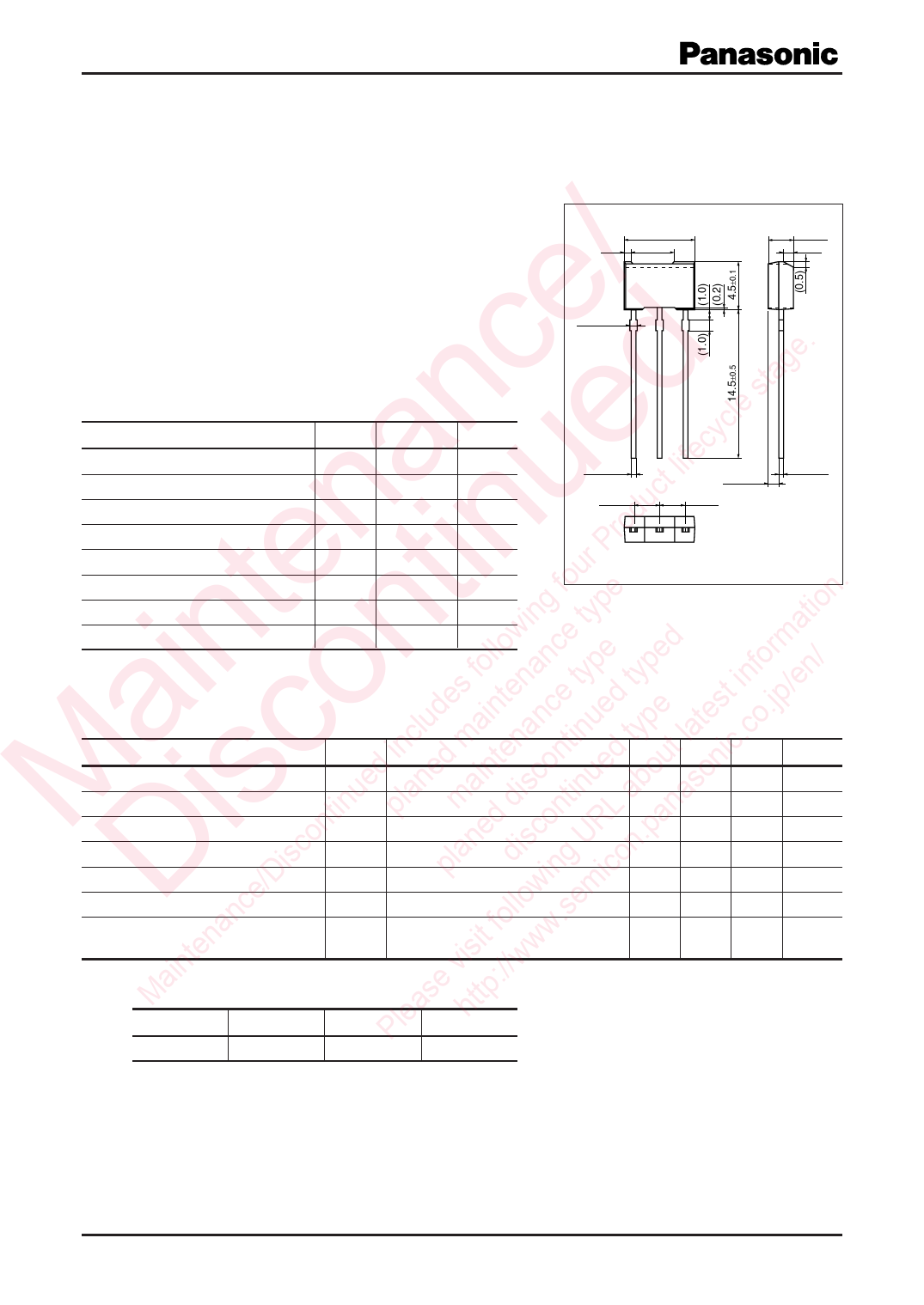
6.9±0.1
0.7 4.0
0.65 max.
Unit: mm
2.5±0.1
(0.8)
nc d le stage. ■ Absolute Maximum Ratings Ta = 25°C
yc Parameter
Symbol Rating
Unit
a e lifec Collector-base voltage (Emitter open) VCBO
300
V
t Collector-emitter voltage (Base open) VCEO
300
V
n u uc Emitter-base voltage (Collector open) VEBO
7
V
rod Collector current
IC
70
mA
te tin r P Peakcollectorcurrent
ICP
100
mA
fou . Collector power dissipation *
PC
1
W
ing type tion Junction temperature
Tj
150
°C
w e a Storage temperature
Tstg −55 to +150 °C
in n follo anc pe ped form / Note) *: Copper plate at the collector is more than 1 cm2 in area, 1.7 mm in thickness
0.45+–00..0150
2.5±0.5
1.05±0.05
2.5±0.5
0.45+–00..0150
123
1: Emitter
2: Collector
3: Base
MT-2-A1 Package
a o ludes ainten nce tyued type test ino.jp/en ■ Electrical Characteristics Ta = 25°C ± 3°C
c inc d m tena ntin d ty t la ic.c Parameter
Symbol
Conditions
Min Typ Max Unit
ed ne in co ue ou on Collector-emitter voltage (Base open)
M is tinu pla ma dis tin ab as Emitter-base voltage (Collector open)
on ed con RL an Collector-emitter cutoff current (Base open)
isc lan is U n.p Forward current transfer ratio *
/D p d ing ico Collector-emitter saturation voltage
D nce llow em Transition frequency
a fo .s Collector output capacitance
ten isit ww (Common base, input open circuited)
VCEO
VEBO
ICEO
hFE
VCE(sat)
fT
Cob
IC = 100 µA, IB = 0
300
IE = 1 µA, IC = 0
7
VCE = 120 V, IB = 0
VCE = 10 V, IC = 5 mA
30
IC = 50 mA, IB = 5 mA
VCB = 10 V, IE = −10 mA, f = 200 MHz 50
VCB = 10 V, IE = 0, f = 1 MHz
V
V
1
µA
220
1.2
V
MHz
10
pF
ain e v ://w Note) 1. Measuring methods are based on JAPANESE INDUSTRIAL STANDARD JIS C 7030 measuring methods for transistors.
M as ttp 2. *: Rank classification
Ple h Rank
P
Q
R
hFE
30 to 100
60 to 150 100 to 220
Publication date: February 2003
SJC00181CED
1
Share Link: 