IC741 Просмотр технического описания (PDF) - Unspecified
Номер в каталоге
Компоненты Описание
производитель
IC741 Datasheet PDF : 7 Pages
| |||
difference in voltage between the two input connections and nothing more. When that input voltage
difference is exactly zero volts, we would (ideally) expect to have exactly zero volts present on the
output. However, in the real world this rarely happens. Even if the op-amp in question has zero
common-mode gain, the output voltage may not be at zero when both inputs are shorted together.
This deviation from zero is called offset. A perfect op-amp would output exactly zero volts with
both its inputs shorted together and grounded. However, most op-amps off the shelf will drive their
outputs to a saturated level, either negative or positive.
Offset voltage will tend to introduce slight errors in any op-amp circuit. So how do we compensate
for it? There are usually provisions made by the manufacturer to trim the offset of a packaged op-
amp. Usually, two extra terminals on the op-amp package are reserved for connecting an external
“trim” potentiometer. These connection points are labeled offset null.
2.3 Input bias current
Inputs on an op-amp have extremely high input impedances. That is, the input currents entering or
exiting an op-amp’s two input signal connections are extremely small. For most purposes of op-amp
circuit analysis, we treat them as though they don’t exist at all. We analyze the circuit as though
there was absolutely zero current entering or exiting the input connections.
This idyllic picture, however, is not entirely true. Op-amps, especially those op-amps with bipolar
transistor inputs, have to have some amount of current through their input connections in order for
their internal circuits to be properly biased. These currents, logically, are called bias currents. Under
certain conditions, op-amp bias currents may be problematic. The following circuit illustrates one
of those problem conditions:
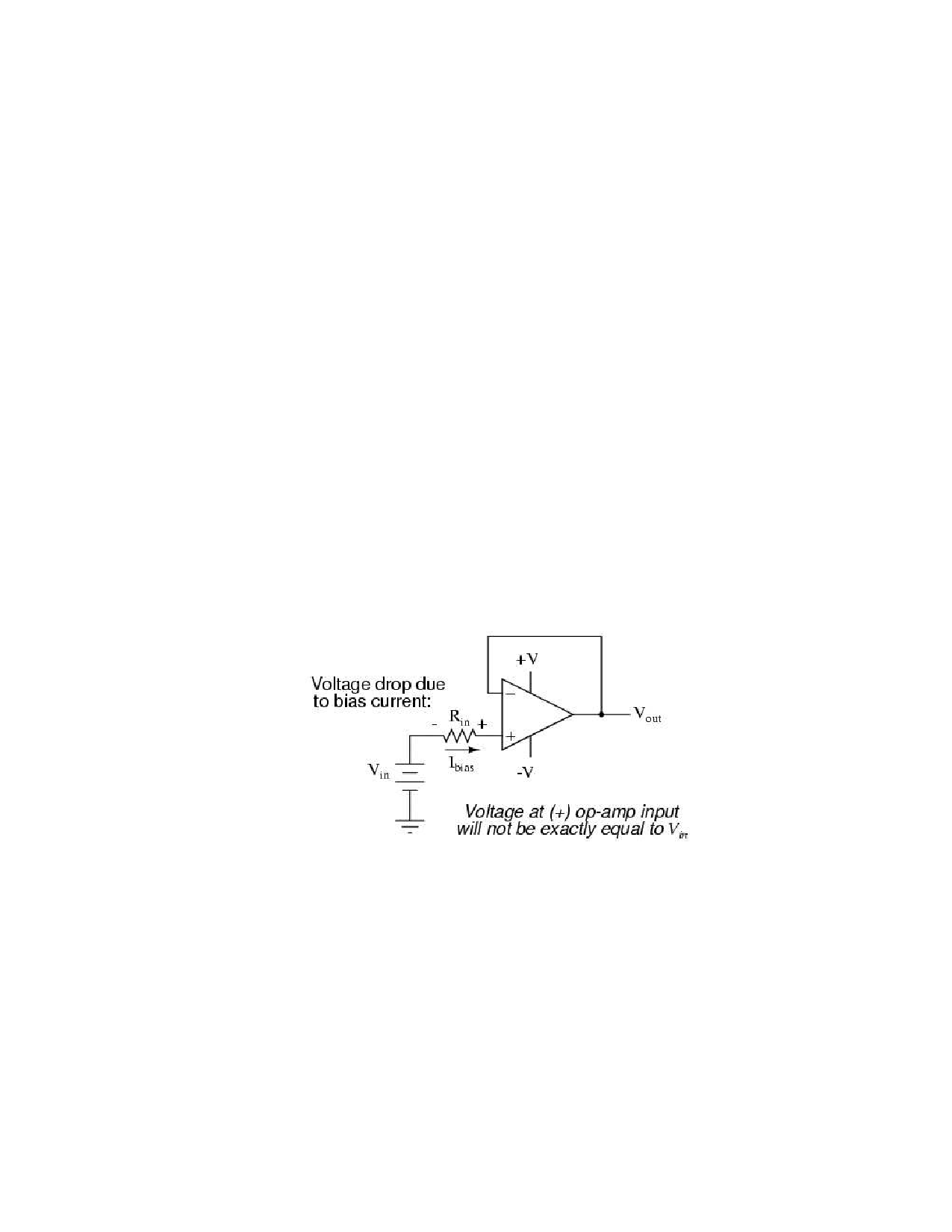
Another way input bias currents may cause trouble is by dropping unwanted voltages across circuit
resistances. Take this circuit for example:
We expect a voltage follower circuit such as the one above to reproduce the input voltage precisely
at the output. But what about the resistance in series with the input voltage source? If there is
any bias current through the noninverting (+) input at all, it will drop some voltage across Rin,
thus making the voltage at the noninverting input unequal to the actual Vin value. Bias currents
are usually in the microamp range, so the voltage drop across Rin won’t be very much, unless Rin
is very large.
3
Share Link: 