ALTAIR04-900TR Просмотр технического описания (PDF) - STMicroelectronics
Номер в каталоге
Компоненты Описание
производитель
ALTAIR04-900TR Datasheet PDF : 29 Pages
| |||
ALTAIR04-900
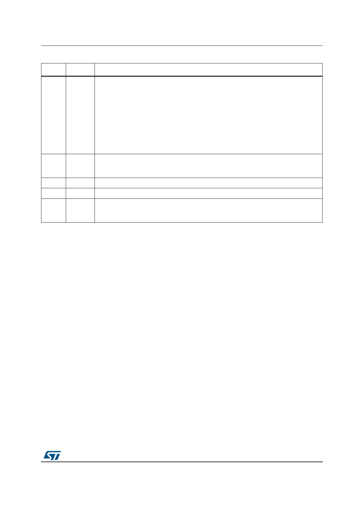
Pin connection
Table 1. Pin functions (continued)
Number Name
Function
Transformer demagnetization sensing for quasi-resonant operation. Input/output voltage
monitoring. A negative-going edge triggers the MOSFET turn-on. The current sourced by the
pin during on-time is monitored to compensate the internal delay of the current sensing
circuit and achieve a CC regulation independent of the mains voltage. If this current does not
exceed 50 µA, either a floating pin or a low input voltage is assumed, the device is stopped
6
ZCD/FB and restarted after Vcc has dropped below 5 V. Besides, the pin voltage is sampled-and-held
right at the end of the transformer demagnetization to get an accurate image of the output
voltage to be fed to the inverting input of the internal transconductance-type error amplifier,
whose non-inverting input is 2.5 V. The maximum IZCD/FB sunk/sourced current doesn’t
exceed ±2 mA (AMR) in all Vin range conditions. No capacitor is allowed between the pin
and the auxiliary transformer.
Output of the internal transconductance error amplifier. The compensation network is placed
7
COMP between this pin and GND to achieve stability and good dynamic performance of the voltage
control loop.
8-11
N.A Not available. These pins must be left not connected.
12
N.C Not internally connected.
13 to 16
DRAIN
Drain connection of the internal power section. The internal high voltage start-up generator
sinks current from these pins as well. Pins are connected to the internal metal frame to
facilitate heat dissipation.
DocID18211 Rev 3
5/29
29
Share Link: 