SD3114-6R8-R Просмотр технического описания (PDF) - Cooper Bussmann, Inc.
Номер в каталоге
Компоненты Описание
производитель
SD3114-6R8-R Datasheet PDF : 3 Pages
| |||
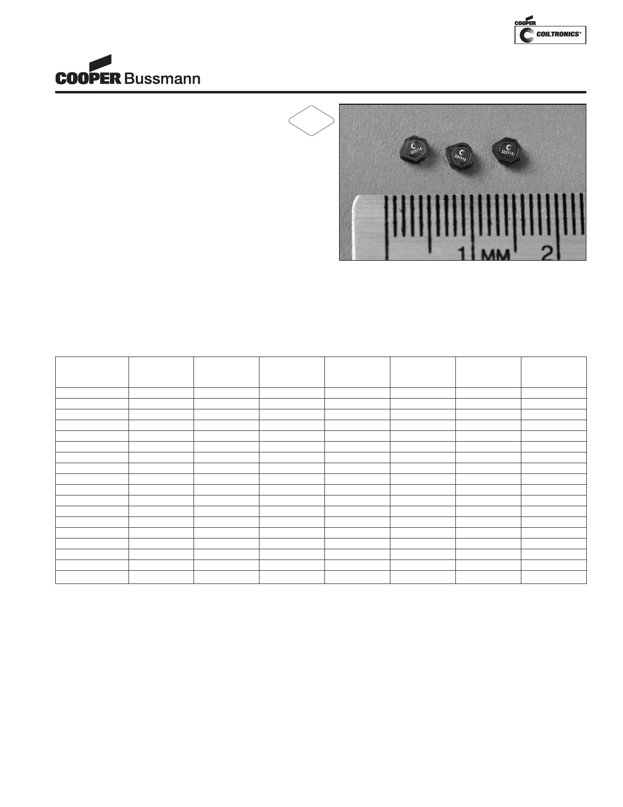
SD3114 Series
Low Profile Power Inductors
Description
• 125°C maximum total temperature operation
• 3.1mm x 3.1mm x 1.4mm shielded drum core
• Ferrite core material
• Inductance range from 1.0uH to 330uH
• Current range from 2.59 Amps to 0.106 Amps
• Frequency range up to 4MHz
RoHS
2002/95/EC
Applications
• Cellular phones, Digital cameras, CD players, PDA’s
• Small LCD displays
• LED driver and LED flash circuits
• Hard disk drives
• Backlighting
• EL panel
Environmental Data
• Storage temperature range: -40°C to +125°C
• Operating temperature range: -40°C to +125°C
(range is application specific)
• Solder reflow temperature: +260°C max. for 10 seconds
maximum
Packaging
• Supplied in tape and reel packaging, 4100 per reel
Part Number
SD3114-1R0-R
SD3114-1R5-R
SD3114-2R2-R
SD3114-3R3-R
SD3114-4R7-R
SD3114-6R8-R
SD3114-8R2-R
SD3114-100-R
SD3114-150-R
SD3114-220-R
SD3114-330-R
SD3114-470-R
SD3114-680-R
SD3114-820-R
SD3114-101-R
SD3114-151-R
SD3114-221-R
SD3114-331-R
Rated
Inductance
(µH)
1.0
1.5
2.2
3.3
4.7
6.8
8.2
10.0
15.0
22.0
33.0
47.0
68.0
82.0
100.0
150.0
220.0
330.0
OCL (1)
(µH)
1.16+/-30%
1.44+/-30%
2.12+/-30%
3.36+/-30%
4.90+/-30%
6.72+/-30%
8.10+/-30%
10.4+/-30%
14.9+/-20%
22.5+/-20%
33.1+/-20%
47.5+/-20%
68.6+/-20%
81.8+/-20%
101.1+/-20%
149.0+/-20%
220.9+/-20%
329.5+/-20%
Part
Marking
Designator
A
B
C
D
E
F
G
H
I
J
K
L
M
N
O
P
Q
R
(1) Open Circuit Inductance Test Parameters: 100kHz, 0.1V, 0.0Adc.
(2) Irms: DC current for an approximate DT of 40°C without core loss. Derating is
necessary for AC currents. PCB layout, trace thickness and width, air-flow, and
proximity of other heat generating components will affect the temperature rise. It
is recommended that the temperature of the part not exceed 125°C under worst
case operating conditions verified in the end application.
Irms (2)
Amperes
1.60
1.39
1.17
0.95
0.77
0.71
0.68
0.57
0.48
0.43
0.35
0.280
0.239
0.227
0.213
0.172
0.140
0.113
Isat (3)
Amperes
2.35
2.11
1.74
1.38
1.14
0.98
0.89
0.78
0.66
0.53
0.44
0.37
0.305
0.280
0.252
0.207
0.170
0.139
DCR (Ω)
typ. @
20°C
0.058
0.077
0.110
0.167
0.251
0.296
0.329
0.458
0.650
0.821
1.23
1.86
2.62
2.91
3.30
5.07
7.67
11.78
K-factor
(4)
98
79
67
54
45
37
34
30
25
21
17
14
12
11
10
8
6
5
(3) Isat Amperes peak for approximately 30% rolloff (@20°C)
(4) K-factor: Used to determine B p-p for core loss (see graph).
B p-p = K*L*∆I, B p-p(mT), K: (K factor from table), L: (Inductance in uH),
∆I (Peak to peak ripple current in Amps).
Share Link: 