MX1.5KE180A Просмотр технического описания (PDF) - Microsemi Corporation
Номер в каталоге
Компоненты Описание
производитель
MX1.5KE180A
Microsemi Corporation

MX1.5KE180A Datasheet PDF : 7 Pages
| |||
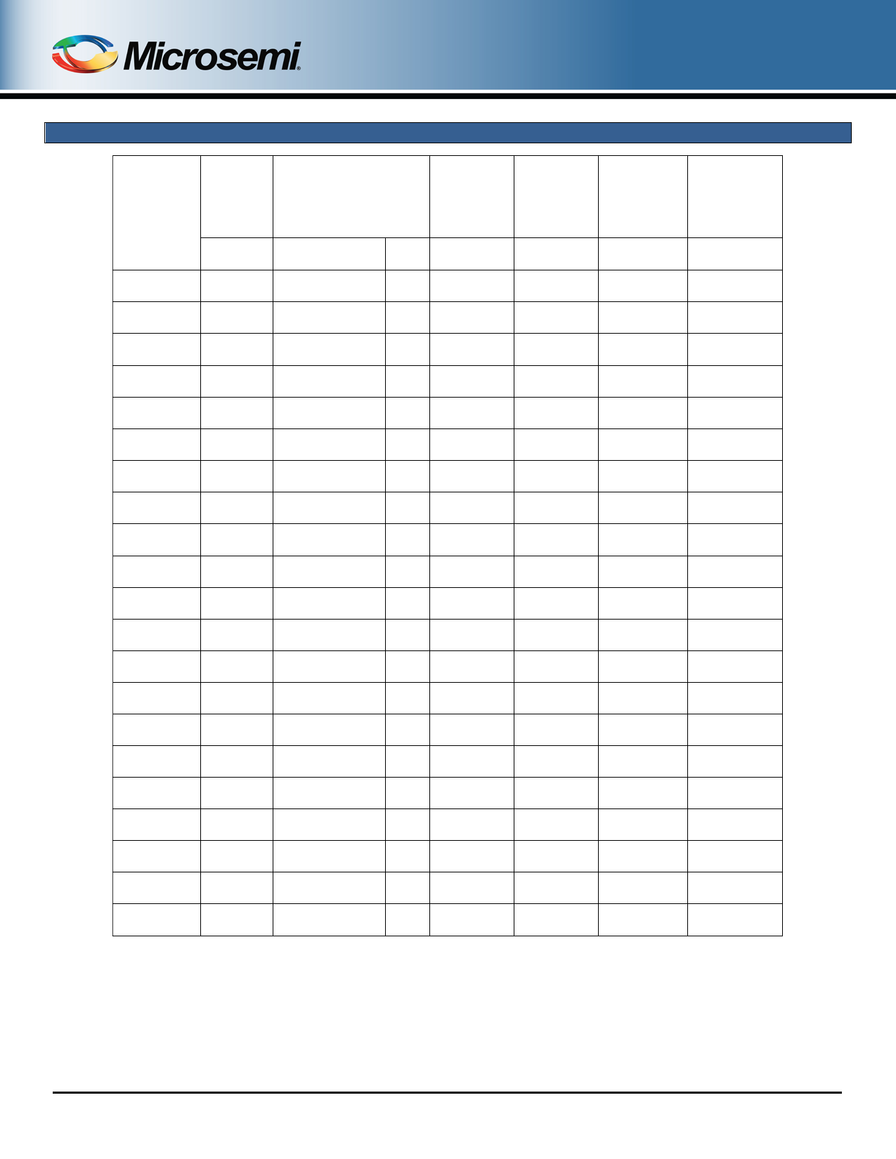
M1.5KE6.8A – M1.5KE400CA(e3)
ELECTRICAL CHARACTERISTICS @ 25 oC
Industry
T ype
Number
M1.5KE6.8A
M1.5KE7.5A
M1.5KE8.2A
M1.5KE9.1A
M1.5KE10A
M1.5KE11A
M1.5KE12A
M1.5KE13A
M1.5KE15A
M1.5KE16A
M1.5KE18A
M1.5KE20A
M1.5KE22A
M1.5KE24A
M1.5KE27A
M1.5KE30A
M1.5KE33A
M1.5KE36A
M1.5KE39A
M1.5KE43A
M1.5KE47A
M1.5KE51A
M1.5KE56A
M1.5KE62A
M1.5KE68A
M1.5KE75A
M1.5KE82A
M1.5KE91A
M1.5KE100A
M1.5KE110A
M1.5KE120A
M1.5KE130A
M1.5KE150A
M1.5KE160A
M1.5KE170A
M1.5KE180A
M1.5KE200A
M1.5KE220A
M1.5KE250A
M1.5KE300A
M1.5KE350A
M1.5KE400A
Rated
Standoff
Voltage
V WM
(Note 1)
Volts
5.80
6.40
7.02
7.78
8.55
9.40
10.22
11.10
12.80
13.60
15.30
17.10
18.80
20.50
23.10
25.60
28.20
30.80
33.30
36.80
40.20
43.60
47.80
53.00
58.10
64.10
70.10
77.80
85.50
94.00
102.00
111.00
128.00
136.00
145.00
154.00
171.00
185.00
214.00
256.00
300.00
324.00
Breakdow n
Voltage
V (BR) @
Volts
I(BR)
Min. Max.
mA
6.45 – 7.14
10
7.13 – 7.88
10
7.79 – 8.61
10
8.65 – 9.55
1
9.50 – 10.50
1
10.50 – 11.60
1
11.40 – 12.60
1
12.40 – 13.70
1
14.30 – 15.80
1
15.20 – 16.80
1
17.10 – 18.90
1
19.00 – 21.00
1
20.90 – 23.10
1
22.80 – 25.20
1
25.70 – 28.40
1
28.50 – 31.50
1
31.40 – 34.70
1
34.20 – 37.80
1
37.10 – 41.00
1
40.90 – 45.20
1
44.70 – 49.40
1
48.50 – 53.60
1
53.20 – 58.80
1
58.90 – 65.10
1
64.60 – 71.40
1
71.30 – 78.80
1
77.90 – 86.10
1
86.50 – 95.50
1
95.00 – 105.00
1
105.00 – 116.00
1
114.00 – 126.00
1
124.00 – 137.00
1
143.00 – 158.00
1
152.00 – 168.00
1
162.00 – 179.00
1
171.00 – 189.00
1
190.00 – 210.00
1
209.00 – 231.00
1
237.00 – 263.00
1
285.00 – 315.00
1
332.00 – 368.00
1
380.00 – 420.00
1
Maximum
Clamping
Voltage
VC @ IPP
Volts
10.5
11.3
12.1
13.4
14.5
15.6
16.7
18.2
21.2
22.5
25.2
27.7
30.6
33.2
37.5
41.4
45.7
49.9
53.9
59.3
64.8
70.1
77.0
85.0
92.0
103.0
113.0
125.0
137.0
152.0
165.0
179.0
207.0
219.0
234.0
246.0
274.0
328.0
344.0
414.0
482.0
548.0
Maximum
Standby
Current
ID @ V WM
µA
1000
500
200
50
10
5
5
5
1
1
1
1
1
1
1
1
1
1
1
1
1
1
1
1
1
1
1
1
1
1
1
1
1
1
1
1
1
1
1
1
1
1
Maximum
Peak Pulse
Current
IPP
(Fig. 2)
A
143.0
132.0
124.0
112.0
103.0
96.0
90.0
82.0
71.0
67.0
59.5
54.0
49.0
45.0
40.0
36.0
33.0
30.0
28.0
25.3
23.2
21.4
19.5
17.7
16.3
14.6
13.3
12.0
11.0
9.9
9.1
8.4
7.2
6.8
6.4
6.1
5.5
4.6
5.0
5.0
4.0
4.0
Maximum
T emperature
Coefficient of
V (BR)
α V (BR)
%/oC
0.057
0.061
0.065
0.068
0.073
0.075
0.078
0.081
0.084
0.086
0.088
0.090
0.092
0.094
0.096
0.097
0.098
0.099
0.100
0.101
0.101
0.102
0.103
0.104
0.104
0.105
0.105
0.106
0.106
0.107
0.107
0.107
0.108
0.108
0.108
0.108
0.108
0.110
0.110
0.111
0.111
0.111
NOTES: 1. Normal selection criteria for TVS devices is by rated stand-off voltage (V WM) and should be equal or greater than dc or continuous peak
operating voltage.
2. TVS devices are tested to maximum peak pulse current (IPP) with clamping voltage monitored. This surge capability is one of the most
significant electrical characteristics of the device and should be considered as part of customer quality inspections.
3. For Bidirectional types having V WM of 8 volts and under, the ID leakage current is doubled. Also for bidirectional parts, the capacitance
will be half that shown in Fig. 2 for zero bias.
4. For unidirectional, the forward voltage (V F) is 3.5 volts maximum at 100 Amps peak for 8.3 ms half-sine wave.
RF01008, Rev. E (11/15/13)
©2013 Microsemi Corporation
Page 4 of 7
Share Link: