FDMC4435BZ –ü—Ä–æ—Å–º–æ—Ç—Ä —Ç–µ—Ö–Ω–∏—á–µ—Å–∫–æ–≥–æ –æ–ø–∏—Å–∞–Ω–∏—è (PDF) - Fairchild Semiconductor
–ù–æ–º–µ—Ä –≤ –∫–∞—Ç–∞–ª–æ–≥–µ
–ö–æ–º–ø–æ–Ω–µ–Ω—Ç—ã –û–ø–∏—Å–∞–Ω–∏–µ
–ø—Ä–æ–∏–∑–≤–æ–¥–∏—Ç–µ–ª—å
FDMC4435BZ Datasheet PDF : 7 Pages
| |||
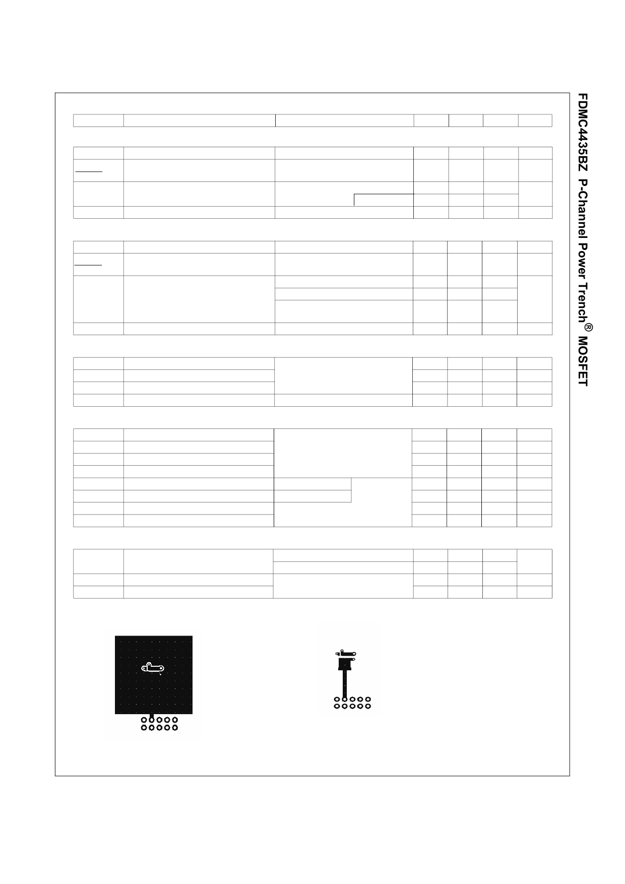
Electrical Characteristics TJ = 25 °C unless otherwise noted
Symbol
Parameter
Test Conditions
Min Typ Max Units
Off Characteristics
BVDSS
'BVDSS
'TJ
Drain to Source Breakdown Voltage
Breakdown Voltage Temperature
Coefficient
IDSS
Zero Gate Voltage Drain Current
IGSS
Gate to Source Leakage Current
ID = -250 PA, VGS = 0 V
ID = -250 PA, referenced to 25 °C
VDS = -24 V,
VGS = 0 V,
TJ = 125 °C
VGS = ±25 V, VDS = 0 V
-30
V
- 22
mV/°C
-1
PA
-100
±10
PA
On Characteristics
VGS(th)
'VGS(th)
'TJ
Gate to Source Threshold Voltage
Gate to Source Threshold Voltage
Temperature Coefficient
rDS(on)
Static Drain to Source On Resistance
gFS
Forward Transconductance
VGS = VDS, ID = -250 PA
ID = -250 PA, referenced to 25 °C
VGS = -10 V, ID = -8.5 A
VGS = -4.5 V, ID = -6.3 A
VGS = -10 V, ID = -8.5 A,
TJ = 125 °C
VDD = -5 V, ID = -8.5 A
-1.0 -1.9 -3.0
V
5.3
mV/°C
15
20
23
37
m:
21
28
24
S
Dynamic Characteristics
Ciss
Coss
Crss
Rg
Input Capacitance
Output Capacitance
Reverse Transfer Capacitance
Gate Resistance
VDS = -15 V, VGS = 0 V,
f = 1 MHz
f = 1 MHz
1540 2045 pF
295 395
pF
260 385
pF
5
:
Switching Characteristics
td(on)
tr
td(off)
tf
Qg
Qg
Qgs
Qgd
Turn-On Delay Time
Rise Time
Turn-Off Delay Time
Fall Time
Total Gate Charge
Total Gate Charge
Gate to Source Charge
Gate to Drain “Miller” Charge
VDD = -15 V, ID = -8.5 A,
VGS = -10 V, RGEN = 6 :
VGS = 0 V to -10 V
VGS = 0 V to -4.5 V
VDD = -15 V,
ID = -8.5 A
10
20
ns
6
12
ns
34
55
ns
20
36
ns
33
46
nC
17
24
nC
5
nC
9
nC
Drain-Source Diode Characteristics
VSD
Source to Drain Diode Forward Voltage VGS = 0 V, IS = -8.5A
VGS = 0 V, IS = -1.9 A
(Note 2)
(Note 2)
0.92 1.5
V
0.75 1.2
trr
Reverse Recovery Time
Qrr
Reverse Recovery Charge
IF = -8.5 A, di/dt = 100 A/Ps
22
ns
11
nC
NOTES:
1. RTJA is determined with the device mounted on a 1 in2 pad 2 oz copper pad on a 1.5 x 1.5 in. board of FR-4 material. RTJC is guaranteed by design while RTCA is determined by
the user's board design.
a. 53 °C/W when mounted on
a 1 in2 pad of 2 oz copper
b.125 °C/W when mounted on
a minimum pad of 2 oz copper
2. Pulse Test: Pulse Width < 300 Ps, Duty cycle < 2.0 %.
3. EAS of 24 mJ is based on starting TJ = 25 °C, L = 1 mH, IAS = -7 A, VDD = -27 V, VGS = -10 V. 100% test at L = 3 mH, IAS = -4 A.
4. The diode connected between the gate and source servers only as protection against ESD. No gate overvoltage rating is implied.
©2010 Fairchild Semiconductor Corporation
2
FDMC4435BZ Rev.D2
www.fairchildsemi.com
Share Link: 