MAX14821 Просмотр технического описания (PDF) - Maxim Integrated
Номер в каталоге
Компоненты Описание
производитель
MAX14821 Datasheet PDF : 30 Pages
| |||
MAX14821
IO-Link Device Transceiver
DO Fault Detection
The device registers a DoFault event when a short circuit
is present at the DO output for 440Fs. A short condition
exists when the load current on the DO driver exceeds
the 135mA (typ) DO current limit. When a short-circuit
condition is detected, the DO driver enters autoretry
mode. In autoretry mode the device periodically checks
whether the error is still present. Autoretry attempts last
for 440µs (typ) and occur every 26ms (typ). When a
DoFault error is detected, the DoFault and DoFaultInt bits
are set, IRQ asserts, and the driver is turned off 440µs
(typ) after the start of the DO faults.
Reverse-Polarity Protection
The device is protected against reverse-polarity connec-
tions on VCC, C/Q, DO, DI, and GND. Any combination
of these pins can be connected to DC voltages up to
40V (max). A short to 40V results in a current flow of less
than 500FA.
Ensure that the maximum voltage between any of these
pins does not exceed 40V.
5V and 3.3V Linear Regulators
The device includes two internal regulators to generate 5V
(V5) and 3.3V (LDO33). LDO5 is specified for 10mA total
external load current (i.e., LDO33 + V5) when bypassed
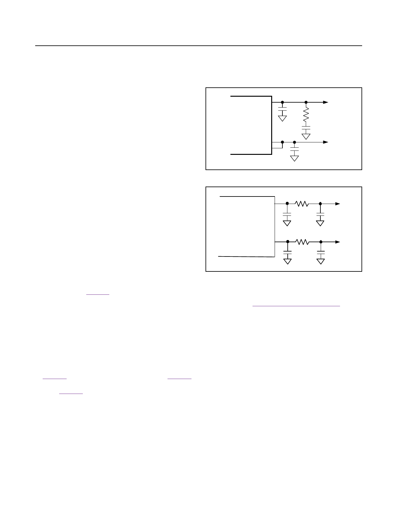
with a 0.1µF capacitor to ground. Add the compensation
network shown in Figure 7 to draw up to 30mA of total
external load current from the 5V LDO. LDO33 is speci-
fied at 20mA. The input of V5, LDOIN, can be powered
from VP, the protected 24V supply output, or to another
voltage in the 7V to 36V range.
If the external circuits that are powered by the linear regulators
require an input bypass capacitance larger than 100nF
for 5V or 1µF for 3.3V, a compensation network must be
added on V5 and/or LDO33. The compensation network
consists of a 10W series resistor and a capacitor equal
to the value required by the external circuit, as shown
in Figure 8. The capacitors C33* and C5* in Figure 8
represent the capacitance required by the external
circuits. Figure 8 does not show any protection diodes
for simplicity.
When the internal 5V LDO is not used, V5 becomes the
supply input for the internal analog and digital functions and
thus has to be supplied externally so that the MAX14820
operates normally. The 5V LDO can be disabled by
connecting LDOIN to V5. Apply an external voltage of
4.75V to 5.25V to V5 when the LDO is disabled.
V5
MAX14821
LDO33
VL
0.1µF
5V
10Ω
1µF
3.3V
1µF
Figure 7. V5 Compensation Network
V5
MAX14821
LDO33
10W
0.1µF
10W
1µF
5V
C5
3.3V
C33
Figure 8. Larger Bypass Capacitance for Powering External
Circuits
Use the LDO33Dis bit in the Mode register to disable
LDO33. See the Mode Register [R1, R0] = [1,1] section
for more information. V5 and LDO33 are not protected
against short circuits.
Power-Up
The C/Q and DO driver outputs and the UV output are
high impedance when VCC, V5, VL, and/or LDO33 voltages
are below their respective undervoltage thresholds during
power-up. UV goes low and the drivers are enabled when
all these voltages exceed their respective undervoltage-
lockout thresholds.
The drivers are automatically disabled if VCC, V5, or VL
falls below its UVLO threshold.
Undervoltage Detection
The device monitors VCC, V5, VL, and optionally LDO33
for undervoltage conditions. UV is high impedance when
any monitored voltage falls below its UVLO threshold.
VCC, V5, and VL undervoltage detection cannot be disabled.
When VCC falls below the VCCUVLO threshold, the UV24 and
UV24Int bits are set, UV asserts high, and IRQ asserts low.
www.maximintegrated.com
Maxim Integrated │ 17
Share Link: 