HLS30ZG-NT Просмотр технического описания (PDF) - Power-One Inc.
Номер в каталоге
Компоненты Описание
производитель
HLS30ZG-NT Datasheet PDF : 10 Pages
| |||
HLS Series DC-DC Converter Data Sheet
48 VDC Input, 30 & 40 Amp Half-Bricks
The general equation (1) for changing the output
voltage on the standard trim modules is invariant, but
the constants in the equation change due to different
internal design.
RTRIM
=
A − B × ΔV
ΔV
,
kΩ
(1)
Where A and B are constants from the table below,
and ΔV is the absolute value of the desired change
in the output voltage in Volts.
Model
HLS30ZG
HLS30ZE
HLS30ZD
HLS40ZA
HLS40ZB
Trim Up
A
B
3.77
6.81
2.07
3.92
1.27
3.92
See
n/a
below
See
n/a
below
Trim Down
A
B
11.58 9.88
3.5
5.61
1.31
4.95
See
n/a
below
See
n/a
below
Negative-Trim, HLS40 models (No P/N suffix)
If an external resistor is placed between the Trim pin
and (+) Sense pin, the output voltage decreases.
The equation determines the required external
resistor value to obtain an output voltage change of
Δ%∗.
Vo*(100-Δ%)-122.5
Rtrim-dn = R1*(---------------------------) - R2 kΩ
Vo*Δ%
If an external resistor is used between Trim pin and
(–) Sense pin, the output voltage increases. The
equation determines the required external resistor
value to obtain an output voltage change of Δ%∗.
122.5*R1
Rtrim-up = (------------- - R2) kΩ
Vo*Δ%
Where R1 and R2 are constants from the table
below
Model
R1 (kΩ)
R2 (kΩ)
HLS30ZG
3.077
6.81
HLS30ZE
1.690
3.92
HLS30ZD
1.039
3.92
HLS40ZA
0. 223
0.15
HLS40ZB
0.475
1
∗ NOTE: Δ% - Percentage output voltage trim down or up.
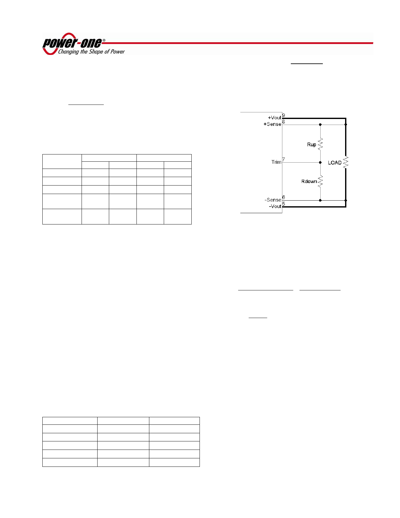
Optional Positive Trim all models (–T, P/N suffix)
The -T option units trim up with a resistor from the
TRIM pin to the (+) Sense pin and trim down with a
resistor from the TRIM pin to the (–) Sense pin as
shown in the Figure 8.
Figure 8. HLS Series Positive Trim Schematic
The equations below determine the trim resistor
value required to achieve a ΔV change in the output
voltage.
RUP
=
Vout×(100+ ΔV
1.225×ΔV%
%)
−
100+ 2×ΔV
ΔV%
%
,kΩ
RDOWN
=
100
ΔV %
−2,
kΩ
where ΔV% is the output voltage change expressed
in percents of the nominal output voltage, Vout.
NOTES:
1. When the output voltage is trimmed up, the output power
from the converter must not exceed its maximum rating. This
is determined by measuring the output voltage on the output
pins, and multiplying it by the output current.
2. In order to avoid creating apparent load regulation
degradation, it is important that the trim resistors are
connected directly to the remote sense pins, and not to the
load or to traces going to the load.
3. The HLS Series converters will trim down further than the
10% limit. In general, this is permissible. The user must
confirm that the results are acceptable in his application.
FEB 17, 2006 revised to JUL 25, 2006
Page 7 of 10
www.power-one.com\
Share Link: 