ML7818A Просмотр технического описания (PDF) - Micro Electronics
Номер в каталоге
Компоненты Описание
производитель
ML7818A Datasheet PDF : 11 Pages
| |||
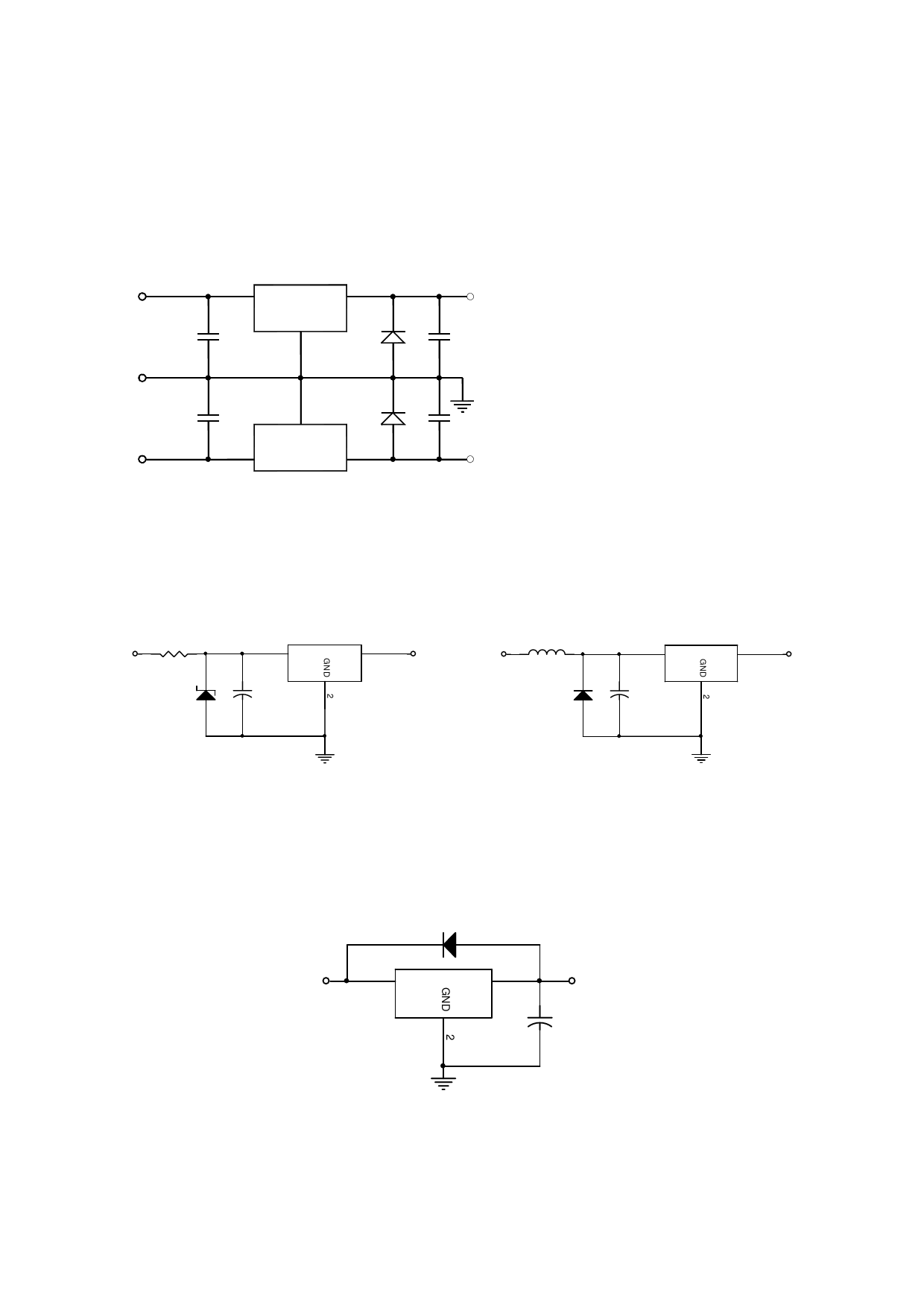
1. Application Circuit
In the following explain only the positive regulator unless otherwise specified. However they can apply to the
negative voltage regulator by easy change.
Positive/Negative Voltage Supply
+Vin
78 series
IN
OUT
0.33uF
GND
D1
COM
0.33uF
-Vin
D2
COM
IN
OUT
79 series
+Vo
0.1uF
Note : In the above positive and negative
power supply application, D1 and D2
should be connected. If D1 and D2
are not connected, either of positive
or negative power supply circuit may
not turns on.
0.1uF
-Vo
2. Note in Application Circuit
(1)
If the higher voltage (above the rated value) or lower voltage (GND-0.5V) is supplied to the input
terminals, the IC may be destroyed. To avoid such a case, a zener diode or other parts of the surge
supressor should be connected as shown below.
R
Vin
Ze ner Diode
1 IN
OUT 3
Vo
+
Capacitor
L
Vin
Diode
1
IN
3
OUT
Vo
+
Capacitor
(2)
If the higher voltage than the input terminal is supplied to the output terminal, the IC may be
destroyed. To avoid input terminal short to the GND or the stored voltage in the capacitor back to the
output terminal, by the large value capacitor connecting to the output terminal application, the SBD
should be required as shown below;
DIODE
Vin
1 IN
OUT 3
Vo
+
Capacitor
* In case of negative voltage regulator, reverse the SBD and capacitor direction.
REV B
Page 8 of 11
Share Link: 