EL7556BCM Просмотр технического описания (PDF) - Intersil
Номер в каталоге
Компоненты Описание
производитель
EL7556BCM Datasheet PDF : 11 Pages
| |||
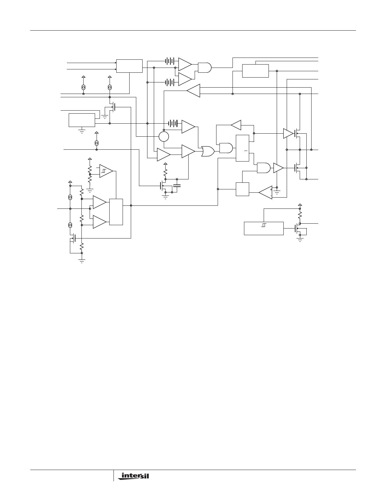
Block Diagram
FB1, Pin1
FB2, Pin 28
VCCDET, Pin 13
CSLOPE, Pin 3
CREF, Pin 27
1.26V
2-1 MUX
OUTEN, Pin 14
VDD
COSC, Pin 4
4V
UVLO
-
S
+
-
R
+
EL7556B
-
+
-
+
-
+
Current Sense
-
+
Σ Current Limit
-
-
+
+ PWM
VDD
RSS
CSS
V2X
LEB TDELAY
Q
R
Q
S
FF
R
S
Zero Cross Detect
Over Temp Sensor
PWRGD, Pin 16
CP, Pin 27
C2V, Pin 26
VHI, Pin 24
VDD and VIN,
Pin 5,6,8
LX, Pin 20-23
VSSP, Pin 9-12,
18-19
OT, Pin 15
VSS, Pin 25
Applications Information
Circuit Description
General
The EL7556B is a fixed frequency, current mode controlled
DC:DC converter with integrated N-channel power
MOSFETs and a high precision reference. The device
incorporates all of the active circuitry required to implement
a cost effective, user-programmable 6A synchronous buck
converter suitable for use in CPU power supplies. By
combining fused-lead packaging technology with an efficient
synchronous switching architecture, high power outputs
(21W) can be realized without the use of discrete external
heat sinks.
Theory of Operation
The EL7556B is composed of 7 major blocks:
1. PWM Controller
2. Output Voltage Mode Select
3. NMOS Power FETS and Drive Circuitry
4. Bandgap Reference
5. Oscillator
9
6. Temperature Sensor
7. Power Good and Power On Reset
PWM Controller
The EL7556B regulates output voltage through the use of
current-mode controlled pulse width modulation. The three
main elements in a PWM controller are the feedback loop
and reference, a pulse width modulator whose duty cycle is
controlled by the feedback error signal, and a filter which
averages the logic level modulator output. In a step-down
(buck) converter, the feedback loop forces the time-averaged
output of the modulator to equal the desired output voltage.
Unlike pure voltage-mode control systems current-mode
control utilizes dual feedback loops to provide both output
voltage and inductor current information to the controller.
The voltage loop minimizes DC and transient errors in the
output voltage by adjusting the PWM duty-cycle in response
to changes in line or load conditions. Since the output
voltage is equal to the time-average of the modulator output
the relatively large LC time constants found in power supply
applications generally results in low bandwidth and poor
transient response. By directly monitoring changes in
inductor current via a series sense resistor the controller’s
response time is not entirely limited by the output LC filter
Share Link: 